Intrinsically-safe ramp for use by rescue personnel

a safety and rescue technology, applied in the field of tools and hardware, can solve the problems of limiting the number of doors that can be secured, the difficulty of transporting many wedges, and the significant fatigue factor, and limiting the number of apparatus that a rescuer may feasibly carry

Inactive Publication Date: 2009-05-07
IBEY JERRY ALAN
View PDF6 Cites 16 Cited by
  • Summary
  • Abstract
  • Description
  • Claims
  • Application Information

AI Technical Summary

Benefits of technology

[0009]It is a principal object of the present invention to provide a multi-functional door-propping ramp for deployment by rescue personnel for the purposes of securing a door in a fixed position and illuminating its doorway with the ramp further being intrinsically-safe such that neither the ramp body nor its electronic components housed therein can cause ignition of potentially-flammable or ignitable substances, and further serving as a multi-purpose visual indicator. It is another object of the present invention to be light-weight and monolithically-constructed of a rigid, transparent and non-metallic material.

Problems solved by technology

Another significant safety issue concerns heat-exhaustion and fatigue of rescuers which is compounded when building structures comprise many rooms, chambers, doorways and stairways that must be climbed and traversed by rescuers encumbered with burdensome and heavy, protective clothing, breathing apparatus, water hoses and a plethora of tools, medical supplies, and other equipment such that the combined weight, coupled with high building temperatures and individual body-heat, becomes a significant fatigue factor.
The Selzer device is capable of sandwiching between a door and its adjacent floor to hold the door securely, however a primary disadvantage of the Selzer device is that it is not low in profile height and otherwise bulky in size and further lacks the capability of ganging a multiplicity of wedges together making the transport of many wedges awkward and difficult whereby a limitation is inherently present as to the number of apparatus that a rescuer may feasibly carry and a limit as to the number of doors that may be secured.
The Loughlin device could serve as a an egress marker in that it houses a beacon which is a strobe light, however, as a door holding device it cannot likely be wedged underneath a door bottom as the ramped portion of its design is steep and not acutely angled and further relies on impact driven tools to mechanically secure itself to an adjacent building structure such as being nailed onto a door frame.
Furthermore, the Loughlin device is tall in profile and has no means to gang a multiplicity of similar devices together.
Another disadvantage of the Loughlin design is that, although it utilizes a beacon for illumination of a doorway, it does not disclose the ability to illuminate in a wide variety of colors and patterns of colors and further discloses that the invention is heat, chemical, water and impact resistant but does not disclose that the entirety of its electronic components are sealed and impervious to such substances whereby the Loughlin invention could be penetrated by potentially flammable substances and thereby short out creating a possible a source of ignition.
Similarly, the very act of striking its pin or spike could cause a spark and thereby be a dangerous source of ignition.
The Loughlin device does not disclose any means to lengthen battery life therefore it is likely that the Loughlin device could not power a strobe with a nine volt battery for any extended length of time whereby the intensity of the strobe is likely to fade rapidly or fail altogether in a short period of time.
A primary disadvantage of the Popps design is that it is relatively large in size whereby it is not likely that even one such device could easily fit within the confines of a utility pocket, furthermore, the Popps device does not disclose any means to gang-together a multiplicity of similar devices and surely would constitute a large, bulky and cumbersome mass should a rescuer attempt to stack many such devices atop one another.
A primary disadvantage of the Stein invention is that a door may utilize a contiguous piano hinge whereby there is no access point to which the invention may be attached, furthermore, the invention may not securely hold the door in a fixed position whereby a falling object or person impacting the door may cause it to swing abruptly, popping out the device and allowing the door to swing about causing possible bodily injury or inadvertently allowing the door to lock closed.
The device discloses no colored lamps or patterns of colors being an object, it is not stackable or ganged one to another and due to its cylindrical shape, is not suitable for sandwiching beneath a door bottom and an adjacent floor.
The device does not disclose that it is in any way sealed, such that its electronic circuitry housed therein could conceivably be a source of ignition should flammable substances come in contact with its electronics.
A primary disadvantage of the Dominguez invention is that is does not provide an acutely-angled edge suitable for tighter fitting doors, it does not house any means of signaling nor by lamps nor reflective attachments.
Furthermore, the Dominguez design is inherently dangerous as the opposing planar members form a scissor-like cutting tool which could literally sever the fingers of a user attempting to deploy the device wherein an abrupt impacting of the door may compress the scissor-like planes and severely injure the user.
Also, if the invention were made of metal parts as supposed, its use would not be safe in and around flammable materials as forces acting upon the door could cause the device to slide or skid across a concrete surface and thereby generate sparks thereby becoming a source of ignition.

Method used


Image

  • Intrinsically-safe ramp for use by rescue personnel
  • Intrinsically-safe ramp for use by rescue personnel
  • Intrinsically-safe ramp for use by rescue personnel

Examples


Embodiment Construction

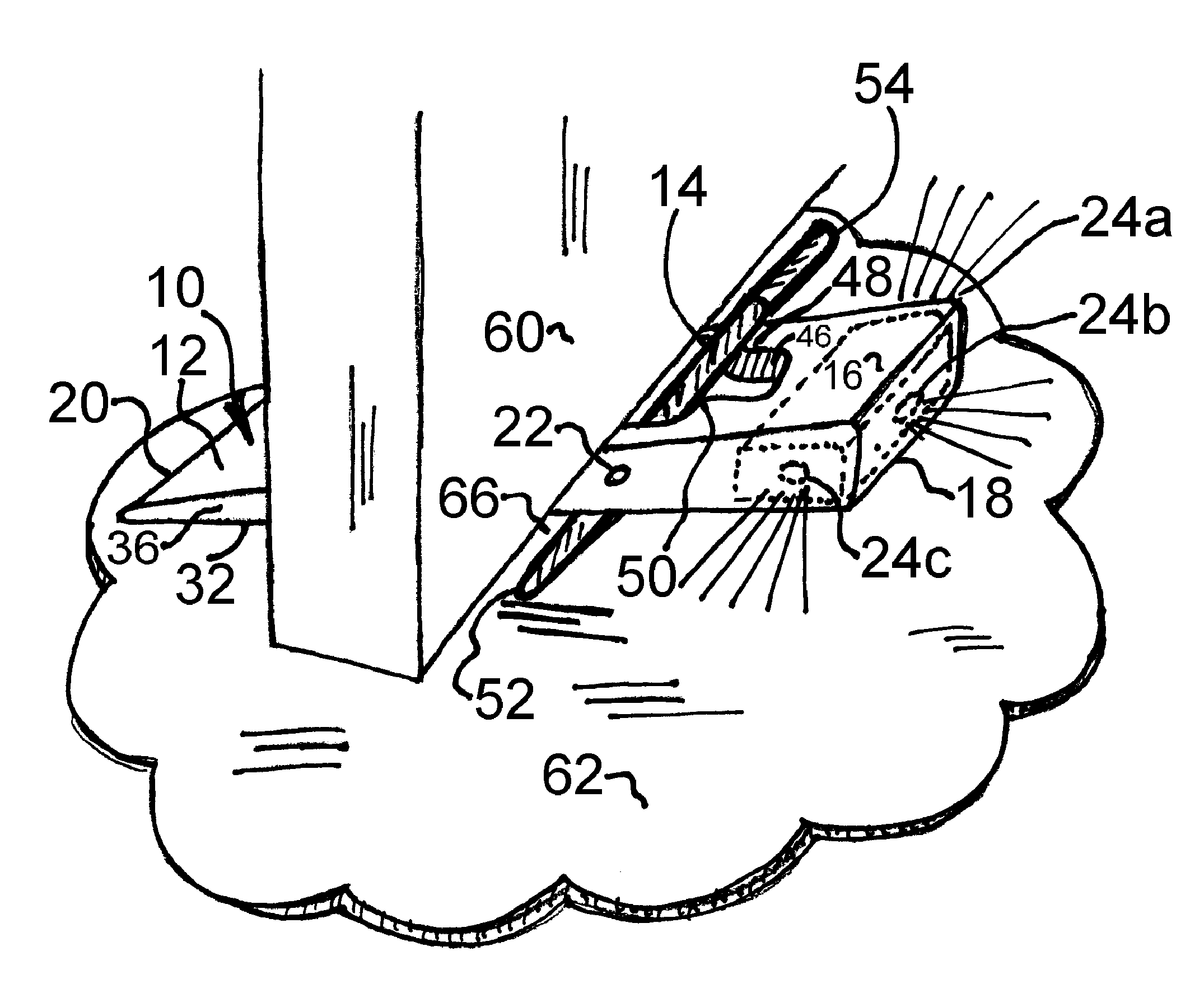
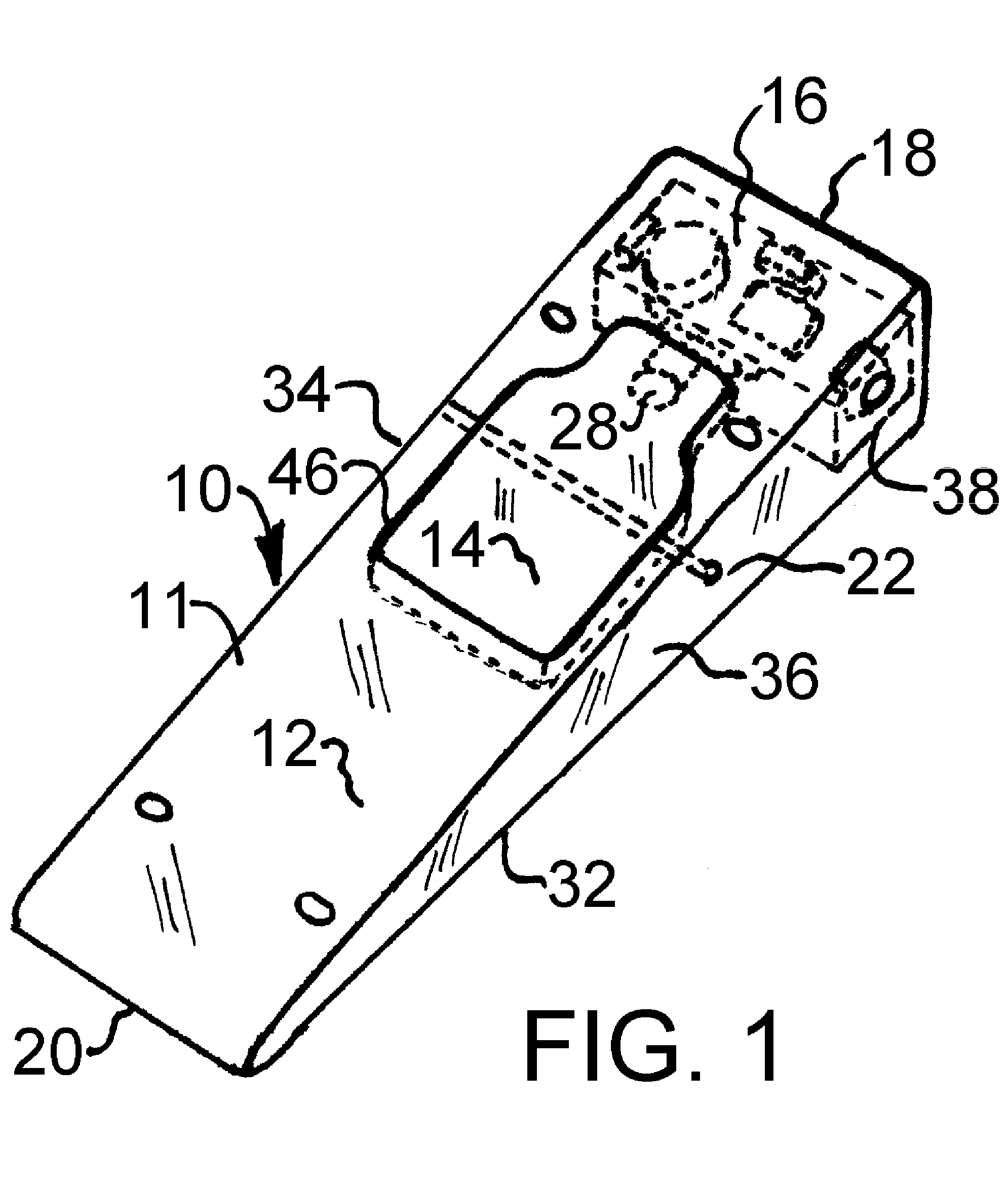
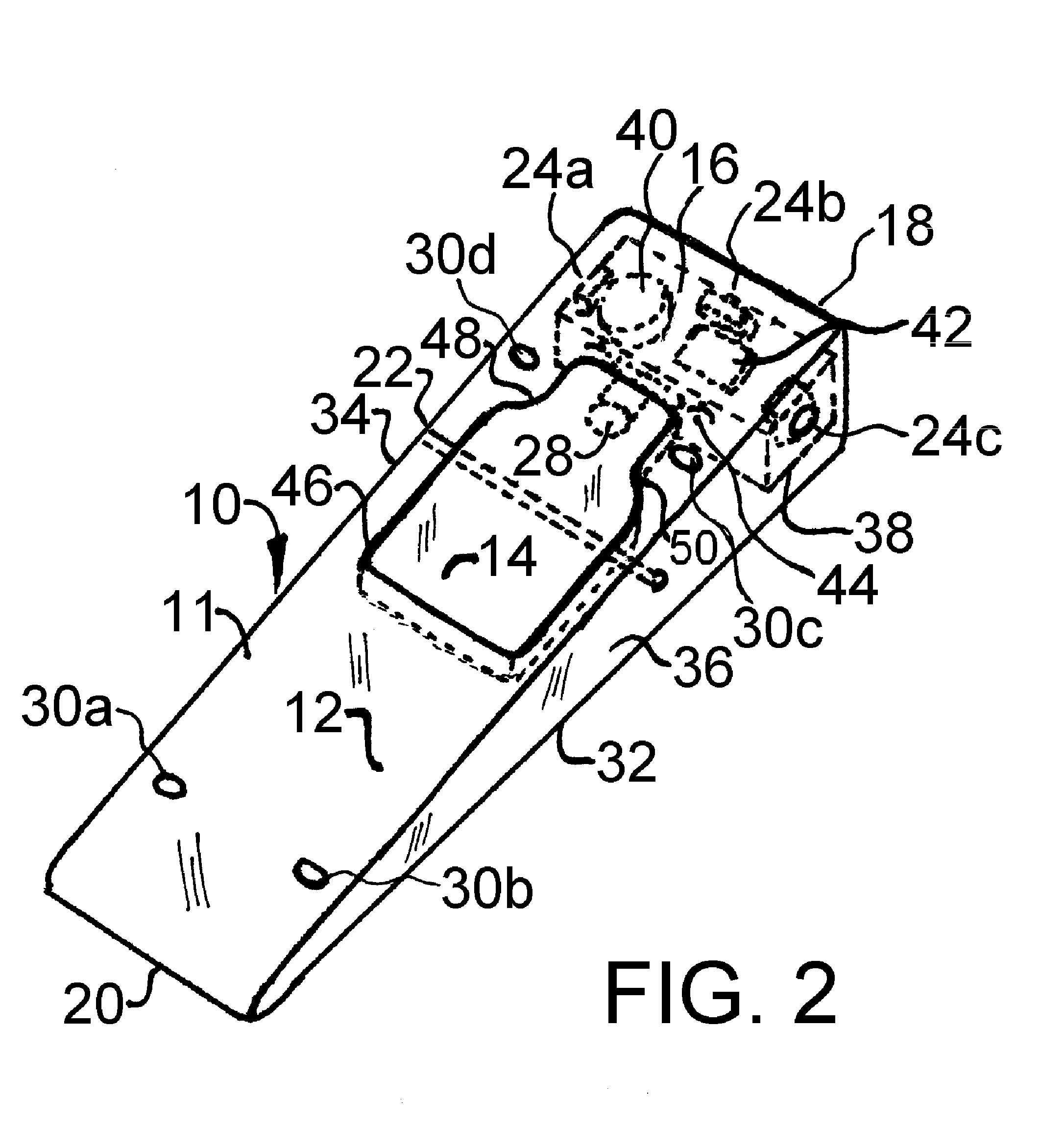
[0043]Referring to the drawings, the ramp of the present invention is generally designated by the numeral 10. As shown in FIG. 1, the ramp 10 is in its normal, collapsed state and bears the major structures of a main ramp body 11 having a planar and textured lower portion 32 with an opposing, inclined and textured upper portion 12. An acutely-angled front edge 20 is opposed by a slightly taller rear edge 18 and supported by integral and monolithically-composed sidewalls 34 and 36 respectively whereby a low-profile ramp is fashioned thereof. Additionally, the ramp body 11 bears a rotatable member 14 which lies within a through opening 46 and is attached with a sturdy metal dowel pin 22 passing therethrough which partially embeds into sidewalls 34 and 36. A magnet 28 is disposed at an edge of the rotatable member 14 which lies in proximity to an electronic module 16 and more specifically to a magnetically-operable switch 44 housed within module 16 wherein a wireless control interface ...


PUM


Abstract

An intrinsically-safe ramp or door prop (10) characterized by a light-weight, transparent ramp having an acutely-angled frontal edge (20), at least one rotatable member or rocker-plate (14) pivotally-attached, for increasing its height, further comprising a kinetic-friction lock, and wireless interface control (28) between an adjacently-housed electronic circuit (16). The circuit (42) is replaceable and sealed and intrinsically-safe for deployment in potentially-flammable or ignitable environments. The electronic circuit further comprises a plurality of multi-colored lamps (24) that visually communicate tactically-significant color signals and bears circuitry (42) to extend battery life wherein lamps may continuously operate for multiple hours. The ramp further comprises attachment points (30) (31) to gang-together a multiplicity of identical ramps whereby fashioning one contiguous block (FIG. 6) of ramps. The block or ramps further being easily manipulated by a user wearing gloves and easily transportable within a utility pocket.

Description

BACKGROUND OF THE INVENTION[0001]The invention relates to tools and hardware deployable by Firefighters and other Search and Rescue Personnel and more specifically to a ramp capable of securing a door in a fixed position where potentially-flammable or ignitable substances may be present and further serving to illuminate a doorway to mark its location for future evidence investigations, indicate egress pathways, and communicate tactically-significant, color-coded, visual signals to other rescuers.[0002]There is a growing concern for the personal safety of Firefighters and other Rescue Personnel when entering buildings which may be compromised such that visibility may be impaired by smoke or darkness, and where potentially-flammable or ignitable substances may come in direct contact with electronic rescue apparatus such that company policies are being implemented wherein such apparatus must be intrinsically-safe or incapable of being a source of ignition. Other safety concerns encompa...

Claims


Application Information

Patent Timeline
Patent Type & Authority Applications(United States)
IPC IPC(8): E05F5/00
CPCA62B3/00E05B17/10E05C17/54Y10T16/95E05Y2800/416E05Y2900/538E05F5/06
Inventor IBEY, JERRY ALAN
Owner IBEY JERRY ALAN
Why Eureka
Try Eureka