Control apparatus and method for gas-turbine engine

a gas turbine engine and control apparatus technology, applied in the direction of machines/engines, analogue processes for specific applications, instruments, etc., can solve the problems of inability to accurately detect the flow rate of the air flowing into the combustion chamber cannot be estimated according to the estimation method employed for the shaft-output engine, and the inability to reduce the power consumption of the engine. , to achieve the effect of enhancing the engine's performance, avoiding power

Inactive Publication Date: 2009-05-07
TOYOTA JIDOSHA KK
View PDF0 Cites 25 Cited by
  • Summary
  • Abstract
  • Description
  • Claims
  • Application Information

AI Technical Summary

Benefits of technology

[0018]The gas-turbine engine is configured in such a manner that a portion of compressed air from the compressor is supplied to the combustion chamber and the other portion of the compressed air is sent to the outside of the engine to be used as source of energy. In the gas-turbine engine, the compressed air and the fuel are mixed together and burned in the combustion chamber, and the turbine is rotated by combustion gas produced in the combustion chamber. In such an extraction engine, as the extracted air flow-rate decreases, power surges are more likely to occur in the compressor. In the gas-turbine engine, the excess power from the turbine increases (consequently, the speed-up performance of the engine is enhanced) by increasing the temperature of the gas at the inlet of the turbine. It is necessary to maintain the temperature of the gas at the inlet of the turbine at a value equal to or lower than the permissible maximum temperature. Therefore, when the engine speed is increased, it is necessary to maintain the temperature of the gas at the inlet of the turbine as high as possible to the extent that power surges do not occur in the compressor. Therefore, when the engine speed is increased, the target flow-rate of the air supplied to the combustion chamber when the operating state is near the border of the surging range of the compressor is obtained, and the target temperature of the gas at the inlet of the turbine is obtained. The control apparatus obtains the flow-rate of the fuel supplied to the combustion chamber when the engine speed is increasing, based on the target flow-rate of the air supplied to the combustion chamber. At the obtained flow-rate of the fuel supplied to the combustion chamber, the target temperature of the gas at the inlet of the turbine is maintained at a value near the permissible maximum temperature. As described above, the control apparatus is able to execute the optimum combustion control at the engine speed-up time while avoiding occurrence of power surges, even if the extracted air flow-rate changes.
[0019]The control apparatus according to the second aspect of the invention may further include: an extracted air flow-rate adjustment unit that releases air from the compressor; and a released air flow-rate adjustment unit that adjusts a flow-rate of the air released from the compressor by the extracted air flow-rate adjustment unit so that the target temperature of the gas at the inlet of the turbine matches a permissible maximum temperature, when the engine speed is increasing. The control apparatus adjusts the flow-rate of the air released from the compressor by the extracted air flow-rate adjustment unit to adjust the flow-rate of the air taken out from the compressor so that the target temperature of the gas at the inlet of the turbine matches the permissible maximum temperature at the engine speed-up time. Adjusting the extracted air flow-rate in the above-described manner makes it possible to maintain the temperature of the gas at the inlet of the turbine at a value near the permissible maximum temperature while avoiding power surges in the compressor. As a result, it is possible to increase the excess power from the turbine. Consequently, the speed-up performance of the engine is enhanced.
[0020]According to the aspects of the invention described above, it is possible to accurately obtain the flow-rate of the air supplied to the combustion chamber, etc. without using means for performing direct measurement, and to the execute the optimum combustion control.

Problems solved by technology

Therefore, the flow-rate of the air compressed by the compressor does not match the flow-rate of the air flowing into a combustion chamber.
Therefore, in the extraction engine, the flow-rate of the air flowing into the combustion chamber cannot be estimated according to an estimation method employed for a shaft-output engine.
Accordingly, the flow-rate of the air flowing into the combustion chamber cannot be accurately detected.
Therefore, it is difficult to directly measure the air flow-rate, for example, the flow-rate of the extracted air, because the power output from the engine is reduced under the influence of, for example, an increase in a pressure loss in a passage.
As a result, in a conventional extraction engine, the optimum control over the combustion that takes place in a combustion chamber cannot be executed, because the flow-rate of the air flowing into the combustion chamber cannot be accurately detected.

Method used


Image

  • Control apparatus and method for gas-turbine engine
  • Control apparatus and method for gas-turbine engine
  • Control apparatus and method for gas-turbine engine

Examples


Embodiment Construction

[0042]Hereafter, a control apparatus for a gas-turbine engine according to an embodiment of the invention will be described with reference to the accompanying drawings.

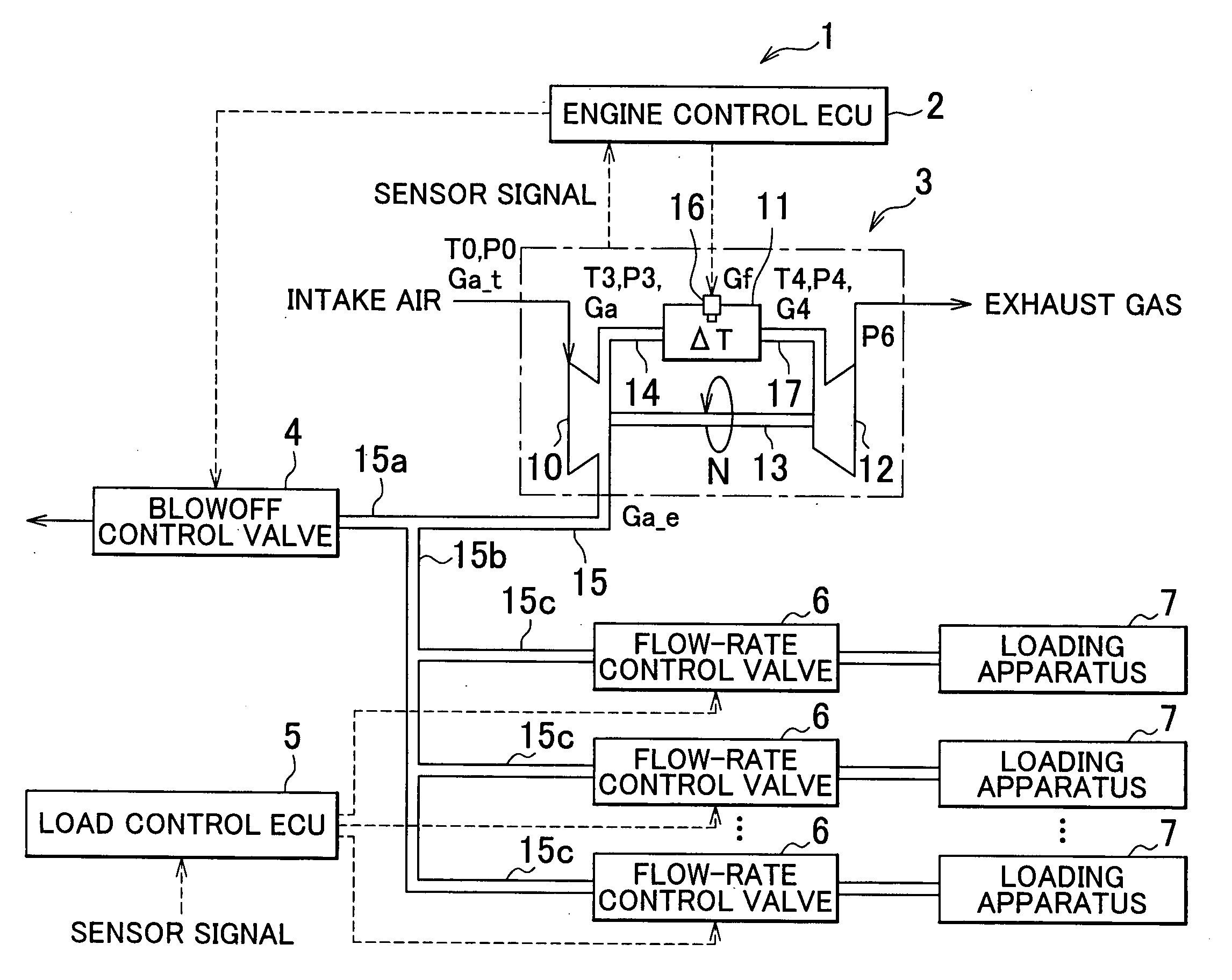
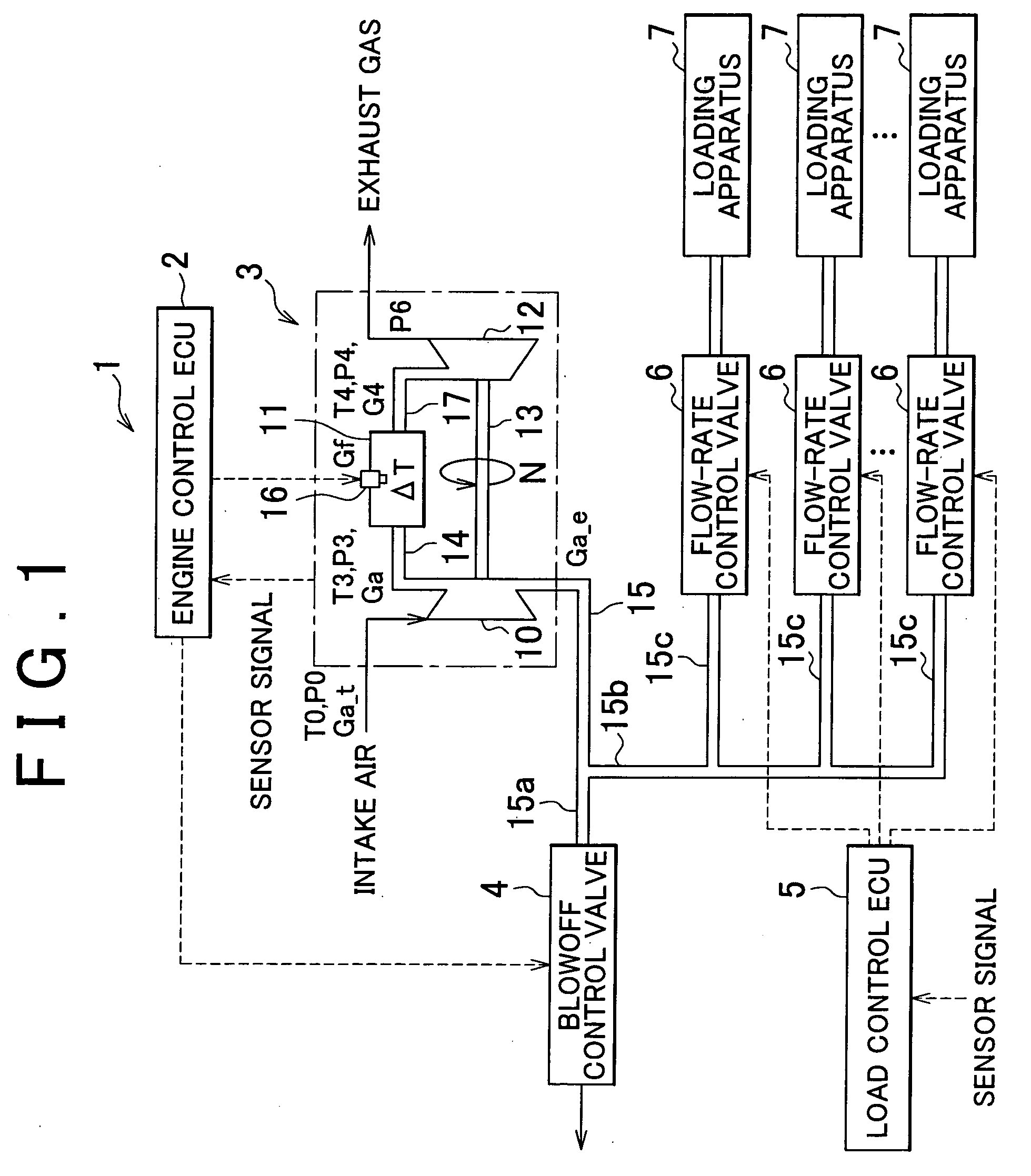
[0043]A control apparatus for a gas-turbine engine according to an embodiment of the invention is applied to an engine control ECU that executes a combustion control over a uniaxial extraction gas-turbine engine. According to the embodiment of the invention, the compressed air taken out from the gas-turbine engine is used as the energy for a loading apparatus, and a load control ECU that executes a drive control over the loading apparatus is also provided. In the embodiment of the invention, a system that is formed of the gas-turbine engine, the loading apparatus, the engine control ECU, the load control ECU, etc. is referred to as a gas-turbine engine system.

[0044]A gas-turbine engine system 1 will be described with reference to FIGS. 1 and 2. FIG. 1 is a view showing the configuration of the gas-turbine engine syste...


PUM


Abstract

There is provided a control apparatus for a gas-turbine engine which is configured in such a manner that a portion of compressed air from a compressor is supplied to a combustion chamber and the other portion of the compressed air is sent to the outside of the engine to be used as source of energy, and a turbine is rotated by combustion gas produced in the combustion chamber. The control apparatus executes the optimum combustion control in an extraction engine. The control apparatus calculates the physical quantity related to the air in the gas-turbine engine using the turbine flow-rate coefficient in the range in which the turbine chokes.

Description

INCORPORATION BY REFERENCE[0001]The disclosure of Japanese Patent Application No. 2006-334896 filed on Dec. 12, 2006 including the specification, drawings and abstract is incorporated herein by reference in its totalty.BACKGROUND OF THE INVENTION[0002]1. Field of the Invention[0003]The invention relates to a control apparatus and method for an extraction gas-turbine engine which is configured in such a manner that the compressed air from a compressor is sent to the outside of the engine to be used as source of energy.[0004]2. Description of the Related Art[0005]In a gas-turbine engine, air is taken into a compressor and compressed therein. Then, the compressed air is sent to a combustion chamber, mixed with the fuel, and burned therein. A turbine is rotated by the combustion gas. One type of gas-turbine engines is a shaft-output engine which outputs power through a rotating shaft connected to a turbine. Another type of gas-turbine engines is an extraction engine. The engine of this ...

Claims


Application Information

Patent Timeline
Patent Type & Authority Applications(United States)
IPC IPC(8): F02C6/04
CPCF02C9/18F02C6/08
Inventor FUKUDA, DAIKI
Owner TOYOTA JIDOSHA KK
Why Eureka
Try Eureka