Method for Manufacturing a Composite Construction Element

a construction element and composite technology, applied in the field of manufacturing a composite construction element, can solve problems such as unsatisfactory folds or angles

Active Publication Date: 2009-05-07
FITS HLDG
View PDF9 Cites 12 Cited by
  • Summary
  • Abstract
  • Description
  • Claims
  • Application Information

AI Technical Summary

Benefits of technology

[0028]In a subsequent step, the edge section can then be bent or folded with respect to the main body. In a preferred embodiment of the method according to the invention, the recess extends up to the other cover layer and this other cover layer is heated up to but not above the glass transition temperature and subsequently bent to form a bend with a relatively large radius. The bent recess consisting of an uninterrupted cover layer, reinforcing layer and/or edges of the interrupted cover layer along the incision is sufficiently strong and impact-resistant to act as connecting strut, where otherwise an additional separate (meta

Problems solved by technology

Thus, the excess material is prevented from bulging outwar

Method used


Image

  • Method for Manufacturing a Composite Construction Element
  • Method for Manufacturing a Composite Construction Element
  • Method for Manufacturing a Composite Construction Element

Examples


Embodiment Construction

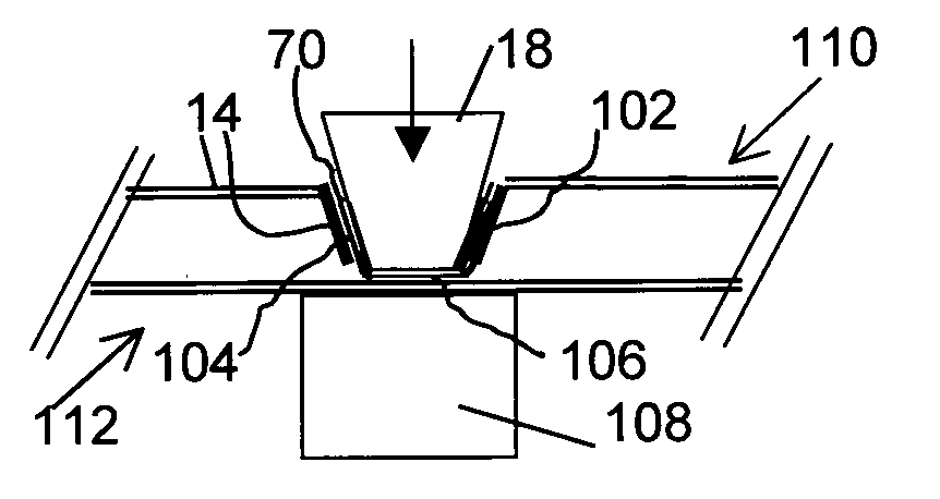
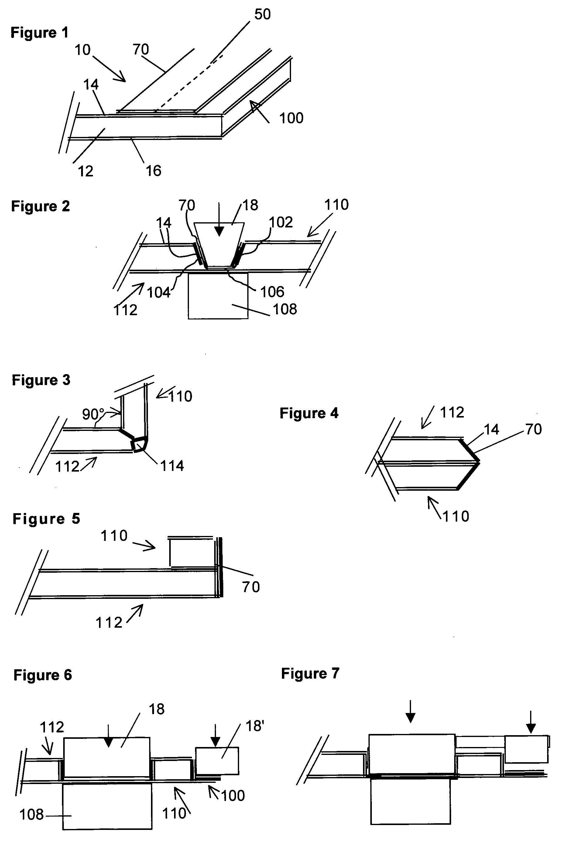
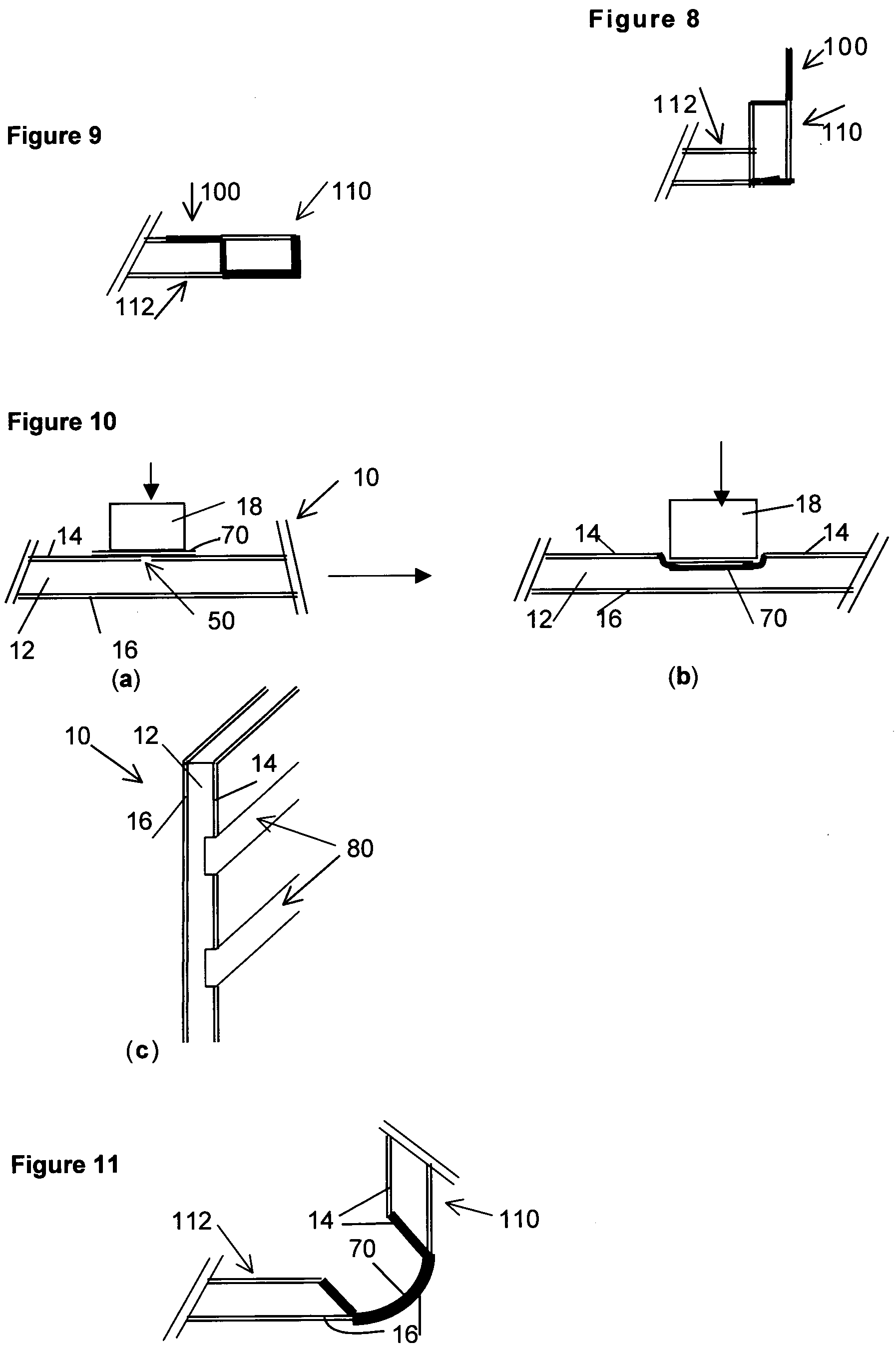
[0054]FIG. 1 shows a thermoplastic sandwich panel 10 which comprises an in-situ foamed core layer 12. Fiber-reinforced thermoplastic cover layers 14 and 16, respectively, are provided at the top of the foam core layer 12 and at the bottom thereof. In a first step, an incision 50 is made in the cover layer 14, parallel to the peripheral edge 100, following which a reinforcing layer 70 of a fiber-reinforced thermoplastic (either prepreg or consolidated laminate) is positioned in such a manner that the incision 50 is covered thereby and the reinforcement ends up in the desired spot in the end product. Subsequently, a hot molding stamp 18 is used to deform the top cover layer 14 at the location of the incision 50 and thus the edges which delimit the incision 50 are folded, with the additional reinforcing layer 70 also simultaneously being deformed and being pressed into the shape of a formed recess 102. See FIG. 2. The recess 102 is delimited by walls 104 and bottom 106, which are made ...


PUM

PropertyMeasurementUnit
Angleaaaaaaaaaa
Angleaaaaaaaaaa
Temperatureaaaaaaaaaa

Abstract

A method for producing a composite construction element comprises the steps of:
  • a) providing a composite construction element, which comprises a thermoplastic core layer between two fiber-reinforced thermoplastic cover layers;
  • b) providing one or more interruptions in a fiber-reinforced thermoplastic cover layer of the panel;
  • c) positioning a fiber-reinforced thermoplastic reinforcing layer over and/or near the interruption;
  • d) deforming situated along the interruption and, if desired, the thermoplastic reinforcing layer, preferably while simultaneously locally compacting the core layer, so that a thermoplastic construction element having a recess which is delimited by fiber-reinforced thermoplastic walls is obtained.

Description

[0001]This application is the National State of International Application no. PCT / NL2007 / 000120 filed May 7, 2007, which claims the benefit of Netherlands patent application number 1031768 filed May 8, 2006, the contents of which are incorporated by reference herein.FIELD OF THE INVENTION[0002]The present invention generally relates to a method for reinforcing and deforming a composite construction element, such as a composite panel, beam or the like, in particular having a thermoplastic sandwich structure, and to objects of this type.BACKGROUND OF THE INVENTION[0003]European patent 431669 discloses a method for manufacturing an object from a thermoplastic sandwich material, in which the normals of at least two surfaces of this object form an angle with respect to one another. This known method comprises at least the steps of softening a part of one of the surfaces of the thermoplastic sandwich material over a distance which corresponds to at least the length of an imaginary folding...

Claims


Application Information

Patent Timeline
IPC IPC(8): B29C53/02B29C43/14B29C48/07B29C48/13B29C48/15B29C48/154B29C48/21
CPCB29C47/0019B29C47/065B29C47/0038B29C47/02B29C53/063B29C67/0011B29C67/0044B29C69/001B29C2793/0081B29K2105/04B29K2105/06B29L2007/002B29L2009/00B29C47/025B29C47/0066B29C47/0033B29C48/15B29C48/07B29C48/13B29C48/001B29C48/0022B29C48/154B29C48/21
Inventor DE GROOT, MARTIN THEODOOR
Owner FITS HLDG
Why Eureka
Try Eureka