Water turbine for generating electricity

a technology of water turbines and turbines, applied in the direction of electric generator control, machines/engines, mechanical equipment, etc., can solve the problem of many years of implementation

Inactive Publication Date: 2009-05-07
BRANCO ANTHONY J
View PDF5 Cites 38 Cited by
  • Summary
  • Abstract
  • Description
  • Claims
  • Application Information

AI Technical Summary

Benefits of technology

[0007]My invention solves the problem of the prior art by providing a modular box-shaped housing having interlocking

Problems solved by technology

This permanent structure requires a major initial outl

Method used


Image

  • Water turbine for generating electricity
  • Water turbine for generating electricity
  • Water turbine for generating electricity

Examples


Embodiment Construction

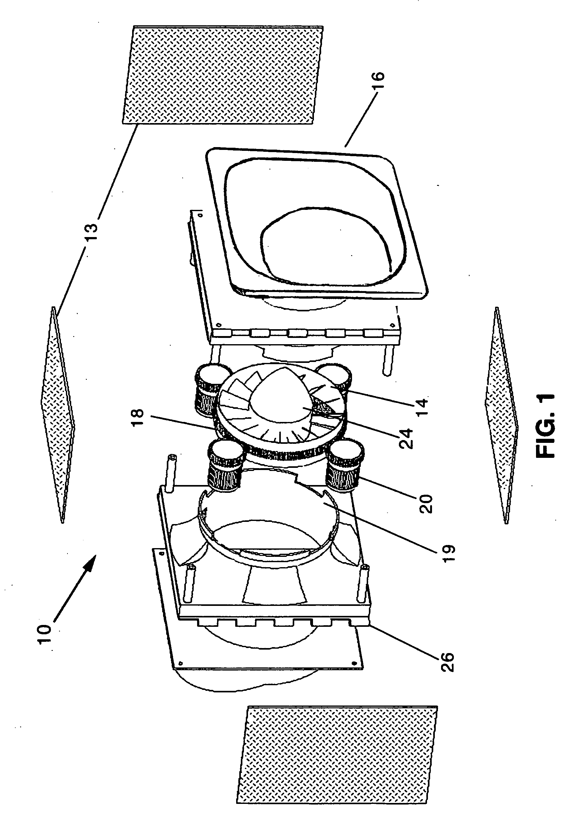
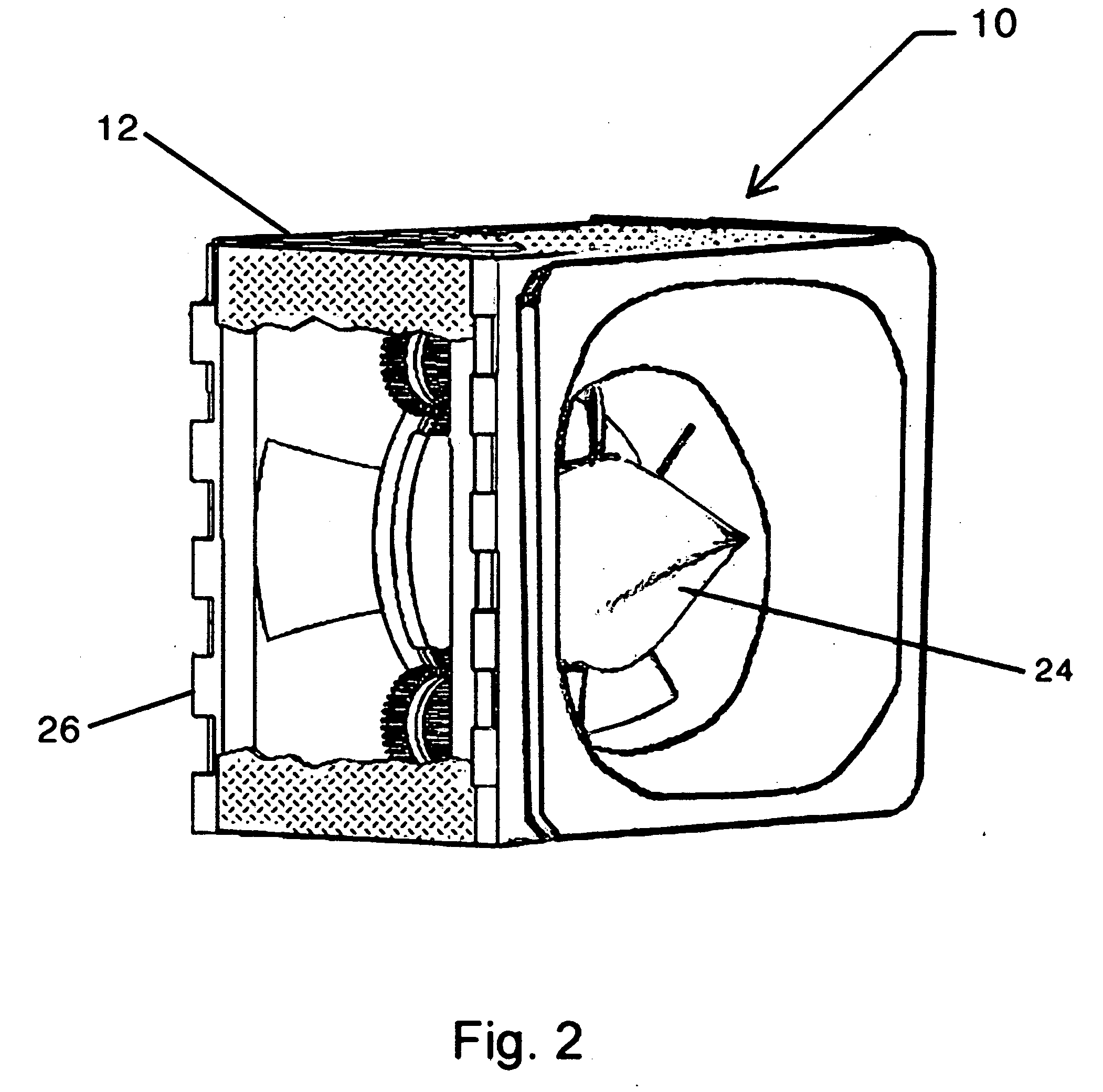
[0017]FIG. 1 is an exploded view of water turbine assembly 10 of the present invention. Turbine 14 is supported and positioned within the throat section 19 of the self supporting box-shaped modular housing 12. Attached to the periphery of the turbine 14 is a ring gear 18 which is in mechanical communication with a plurality of generators 20. This mechanical communication between the ring gear 18 and the generators 20 can take the shape of many well know expediencies within the purview of a person having ordinary skill in the art. Receiver means 16 are positioned and attached to the inlet and outlet of housing 12. Receiver means 16 is designed to collect, concentrate and direct water through the throat section 19 at an accelerated rate. Nose cone 24 mounted on the turbine directs the accelerated water to the distal ends thereof so that maximum torque is transferred to the turbine for producing optimum energy for any given water flow rate. As the water enters the housing 12, the cross...


PUM


Abstract

An array 22 of water turbine assemblies 10 is positioned between two I-beams driven into the bed of a flowing water system. Each water turbine assembly 10 comprises a modular box-shaped housing 12 having an inlet and outlet for accelerating the flow of water therethrough. Turbine 14 has a ring gear 18 positioned about the periphery thereof in mechanical communication with a plurality of generators 20 for converting the kinetic energy of flowing water into electricity. Receiving means 16 are positioned and attached to the inlet and outlet of the housing 12 for collecting, concentrating, directing and accelerating water through the turbine 14 in the throat section 19 of each water turbine assembly 10. Each box-shaped modular housing 12 is structurally communicated with other housings 12 by interlocking mating surfaces 26.

Description

CROSS REFERENCE TO RELATED APPLICATIONS[0001]this application is a continuation-in-part of my copending application Ser. No. 11 / 977,246 filed on Oct. 24, 2007 which in turn is based on Provisional Patent Application 60 / 937,030, filed on Jun. 25, 2007.FEDERALLY SPONSORED RESEARCH[0002]noneSEQUENCE LISTING[0003]noneBACKGROUND OF THE INVENTION[0004]This invention relates to water turbine technology and specifically to the utilization of the available kinetic energy present in the flowing water systems including rivers, streams and canals as well as kinetic energy available in the tidal movement of bays and oceans.[0005]U.S. Pat. No. 4,317,330 (1982) to Brankovics shows the concept of providing a large structural installation having a catch basin formed by a dam wall and a plurality of water chutes each having gates to control the flow of water to a plurality of turbines positioned in each chute. This permanent structure requires a major initial outlay of resources and would take many y...

Claims


Application Information

Patent Timeline
IPC IPC(8): F03B13/10
CPCY02E10/22F03B13/10Y02E10/20
Inventor BRANCO, ANTHONY J.
Owner BRANCO ANTHONY J
Why Eureka
Try Eureka