Power control circuitry, circuitry for analysing a switched power rail, and method of controlling connection of a power source to a switched power rail

a power control circuit and switch technology, applied in the direction of power consumption reduction, electric pulse generator, electric variable regulation, etc., can solve the problems of compromising the measurement more than an indirect approach, adding capacitive load and affecting the turn on characteristic, and difficult to make such analogue voltage measurements in an unintrusive manner. , to achieve the effect of improving the tolerance to process and/or temperature variations

Active Publication Date: 2009-05-07
ARM LTD
View PDF18 Cites 31 Cited by
  • Summary
  • Abstract
  • Description
  • Claims
  • Application Information

AI Technical Summary

Benefits of technology

[0012]Whilst in one embodiment the absolute frequency of the oscillating output signal is determined by the analysis circuitry, for example with reference to a system clock signal, in an alternative embodiment the relative frequency of the oscillating output signal can be determined by comparison with an additional ring oscillator circuit. In particular, in one embodiment, the power control circuitry further comprises: additional ring oscillator circuitry powered from the power source and producing an additional oscillating output signal; the analysis circuitry performing said analysis by comparing frequency of the oscillating output signal with frequency of the additional oscillating output signal and controlling said at least one aspect of the operation of the switch block in dependence on said comparison. The use of an additional ring oscillator circuit in this manner can automatically compensate for process and temperature variations.
[0013]Whilst the ring oscillator circuits can be arranged to operate at different speeds given a particular supply voltage, in one embodiment the additional ring oscillator circuitry and the ring oscillator circuitry are of identical construction. This further improves tolerance to process and / or temperature variations when performing the analysis.

Problems solved by technology

However, to determine the actual characteristics of the switch block, it would be useful to observe one or more properties of the analogue voltage present on the switched power rail, but it is difficult to make such analogue voltage measurements in an unintrusive manner.
Analogue voltage measurements typically require exposing the switched power rail off chip, which then adds capacitive load and itself affects the turn on characteristic.
Another possibility would be to seek to develop mixed-signal analogue-to-digital converters for deployment on-chip, but such direct access techniques may tend to compromise the measurement more than an indirect approach.

Method used


Image

  • Power control circuitry, circuitry for analysing a switched power rail, and method of controlling connection of a power source to a switched power rail
  • Power control circuitry, circuitry for analysing a switched power rail, and method of controlling connection of a power source to a switched power rail
  • Power control circuitry, circuitry for analysing a switched power rail, and method of controlling connection of a power source to a switched power rail

Examples


Embodiment Construction

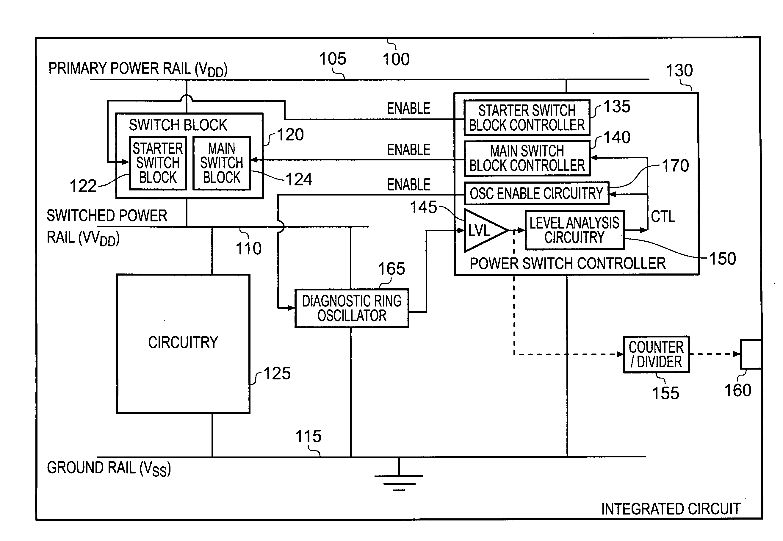
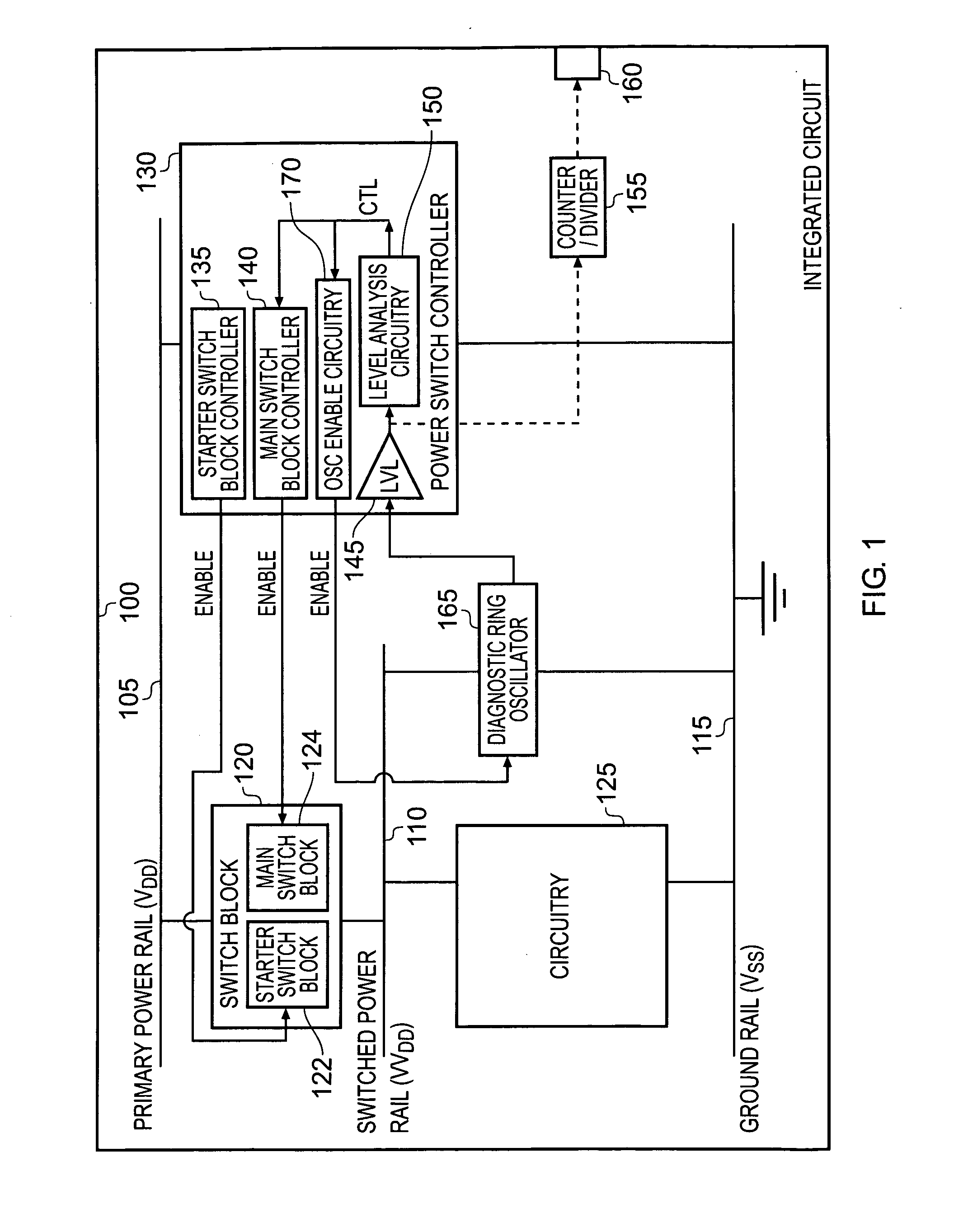
[0049]FIG. 1 illustrates an integrated circuit 100 in accordance with one embodiment of the present invention. The integrated circuit 100 has circuitry 125 used to perform the data processing operations required by the integrated circuit, with the circuitry 125 being connected to the ground rail 115 and receiving its supply voltage from the switched power rail 110. The switched power rail 110 is coupled to the primary supply voltage rail 105 by the switch block 120, whose operation is controlled by the power switching controller 130.

[0050]The switch block 120 may be comprised of a plurality of separate switch block portions which can be separately enabled during a turn on sequence. In one particular embodiment, the switch block 120 includes a starter switch block 122, which itself may consist of a plurality of switch block portions, the starter switch block 122 being enabled during a initial stage of the turn on process so as to pull the voltage on the switched power rail 110 toward...


PUM


Abstract

Power control circuitry is provided for controlling connection of a power source having a source voltage level to a switched power rail to provide power to an associated circuit block. The power control circuitry comprises a switch block for selectively connecting the switched power rail to the power source, and a switch controller for controlling operation of the switch block. A ring oscillator circuit is powered from the switched power rail and produces an oscillating output signal, and analysis circuitry is then used to analyse change in frequency of the oscillating output signal produced by the ring oscillator circuit during a period of time when the switched power rail is not at the source voltage level. The switch controller is then arranged to control at least one aspect of the operation of the switch block in dependence on the analysis. This technique provides a simple and effective digital technique for observing voltage changes on the switched power rail.

Description

BACKGROUND OF THE INVENTION[0001]1. Field of the Invention[0002]The present invention relates to power control circuitry, circuitry for analysing an on-chip switched power rail, and a method of controlling connection of a power source to an on-chip switched power rail.[0003]2. Description of the Prior Art[0004]It is known to provide circuits that include power rails connected via switch blocks to switched power rails. Circuit blocks can then be arranged to draw their power from the switched power rails. The switch blocks may be provided as header switch blocks for connecting a supply voltage rail to a switched supply voltage rail, or may be footer switch blocks for connecting a ground voltage rail with a switched ground voltage rail. Indeed, some circuits may include both header switch blocks and footer switch blocks. The switch blocks are typically constructed using high threshold transistors, and can be used to isolate the switched power rail from the main power rail and according...

Claims


Application Information

Patent Timeline
Patent Type & Authority Applications(United States)
IPC IPC(8): H01H47/20
CPCH03K3/0315H02M3/156H03K19/0016
Inventor FLYNN, DAVID WALTERSCHUTH, LEAH ELIZABETHIDGUNJI, SACHIN SATISH
Owner ARM LTD
Why Eureka
Try Eureka