Distributed electric power generation

Inactive Publication Date: 2009-05-07
BULLIS JAMES KENNETH
View PDF15 Cites 29 Cited by
  • Summary
  • Abstract
  • Description
  • Claims
  • Application Information

AI Technical Summary

Benefits of technology

[0022]The nearly ideal system efficiency comes about because discharged heat, otherwise wasted, is now captured to be used by the household. It replaces

Problems solved by technology

Some design issues still remain.
In the course of choosing the propulsion system for these concepts, it was found that the relative merit of systems was not as simple to determine as originally expected.
However, the amount of carbon dioxide released into the atmosphere as a result of operating that car is not necessarily a simple function of energy efficiency.
Our problem is much worse.
The problem is coal, even though it is now possible to clean much of the health damaging pollutants from the exhausts, the carbon dioxide that is a natural component of air has been shown to be far out of balance.
Further, the cost of a kilowatt-hour of electricity made from natural gas is about three to five times as much as the cost of that unit of electricity made from coal.
Even with large subsidies it does not appear that solar or wind alternatives are likely to make much difference.
The cost of the subsidies is a further burden on the consumer, and although it is not widely protested now, if these methods are widely implemented, the cost will be staggering, as will be the objections.
If electric cars were to be added to the existing load on the electric power system, the problem would be greatly exacerbated.
Unfortunately there appears

Method used


Image

  • Distributed electric power generation
  • Distributed electric power generation
  • Distributed electric power generation

Examples


Embodiment Construction

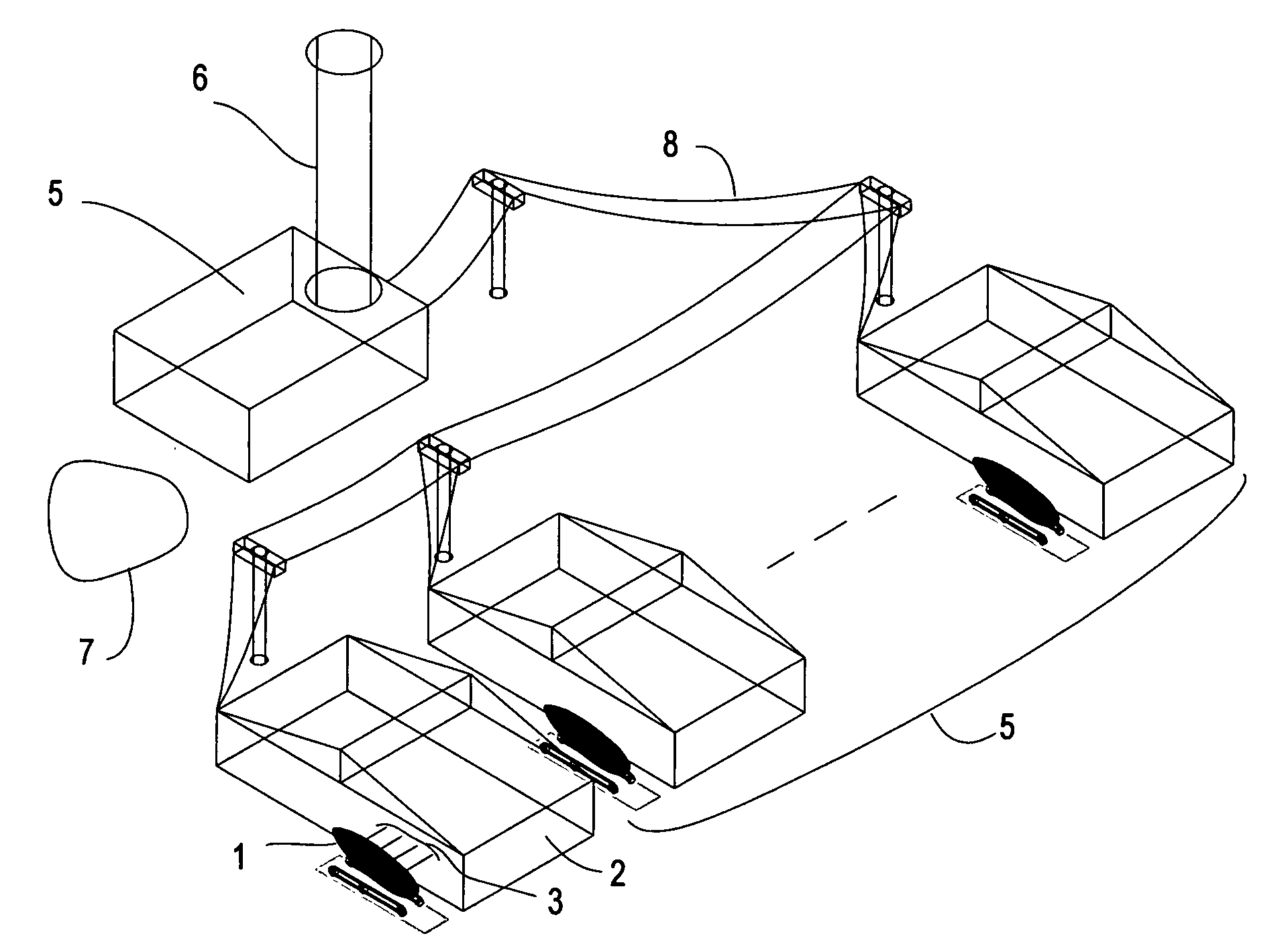
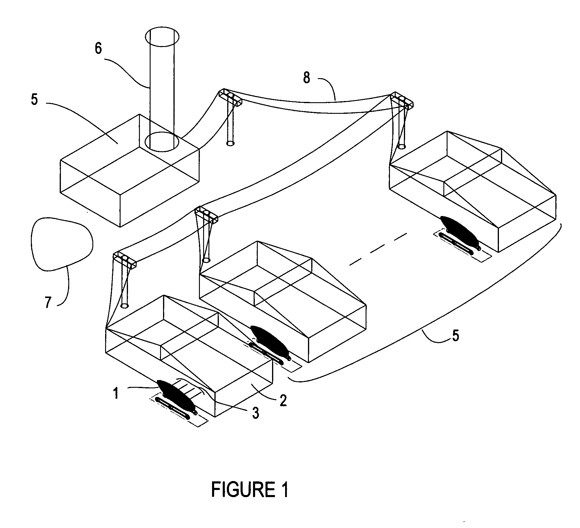
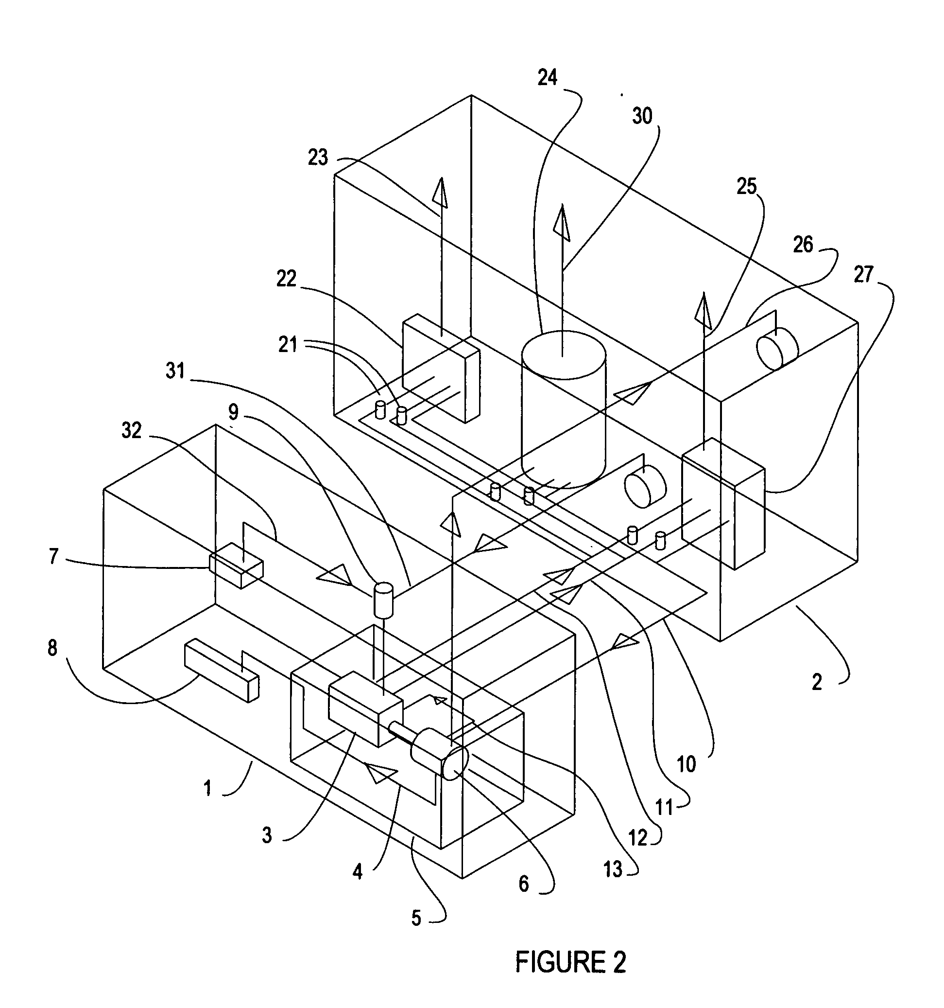
[0029]The high efficiency, narrow vehicle concept of the previously mentioned inventions does much to satisfy the requirements for a transportation system that fits with the distributed living and working choice of the public. Based on the high efficiency vehicle, a complementary arrangement has now been worked out where a system of power generation associated with that transportation system results in reduced carbon dioxide emissions as well as reduced use of fossil fuel in general. Because vehicles are distributed, a distributed power generation system is possible. This distributed power system supports the gains to be made with the high efficiency vehicles by assuring that the source of electricity is not detrimental to the environment, as well as highly efficient in use of resources. There is even an overflow effect where efficiently generated electric power that is surplus to the vehicle needs is available for household use and for use in the electric utility distribution netwo...


PUM


Abstract

An electric power generating system is arranged such that the system efficiency approaches 100%. In the context of this special arrangement, system efficiency is defined as the electrical energy produced divided by the amount of heat energy allocated to its production. All heat energy that is not converted to electric energy is completely used by an associated household. However, high efficiency requires that heat usage by the household is not increased as a result of this arrangement. Unlike most electric power generation, heat is not wasted, so there is no inefficiency.
The motor vehicle includes an electric generator driven by a heat engine, with an optional natural gas connection to the household. The heat from the exhaust and the engine coolant is connected to household devices that make full use of that heat. As needed, operation of the heat engine is regulated such that heat discharge rate does not exceed the rate at which household devices can use that heat. Generated electricity charges vehicle batteries, with surplus going to the household and to the public utility.

Description

[0001]This patent document contains material that is subject to copyright protection. Facsimile reproduction is allowed of the patent document or the patent disclosure as it appears in the Patent and Trademark Office patent file or records as allowed by US patent law, but otherwise all copyright rights are reserved.BACKGROUND OF THE INVENTION[0002]1. Field of the Invention[0003]This present invention relates to electric power generation systems and motor vehicles.[0004]2. Description of the Prior Art[0005]Effective personal transportation design involves a number of requirements. Global warming has become an issue such that the rate of carbon dioxide emission is now a high priority consideration. The fact that world fuel supplies are being depleted and, accordingly, the cost of fossil fuels is going up, along with the international problems that are arising as a result of the oil and gas economy, means that energy efficiency is still an important priority. Safety is an underlying re...

Claims


Application Information

Patent Timeline
IPC IPC(8): H02J7/14B60L11/00H02J7/32
CPCH02J3/38Y02E60/721Y04S10/126Y02E60/00
Inventor BULLIS, JAMES KENNETH
Owner BULLIS JAMES KENNETH
Why Eureka
Try Eureka