
Switching amplifier and its modulation process

a technology of switching amplifier and modulation process, which is applied in the direction of amplifiers, dc amplifiers with modulator-demodulator, amplifiers, etc., can solve the problems of unsatisfactory degree of distortion, increase system cost and size, and detrimental effect on portable applications, so as to achieve low total harmonic distortion and low cost

Inactive Publication Date: 2009-05-07
APEXONE MICROELECTRONICS
View PDF3 Cites 10 Cited by
  • Summary
  • Abstract
  • Description
  • Claims
  • Application Information

AI Technical Summary

Benefits of technology

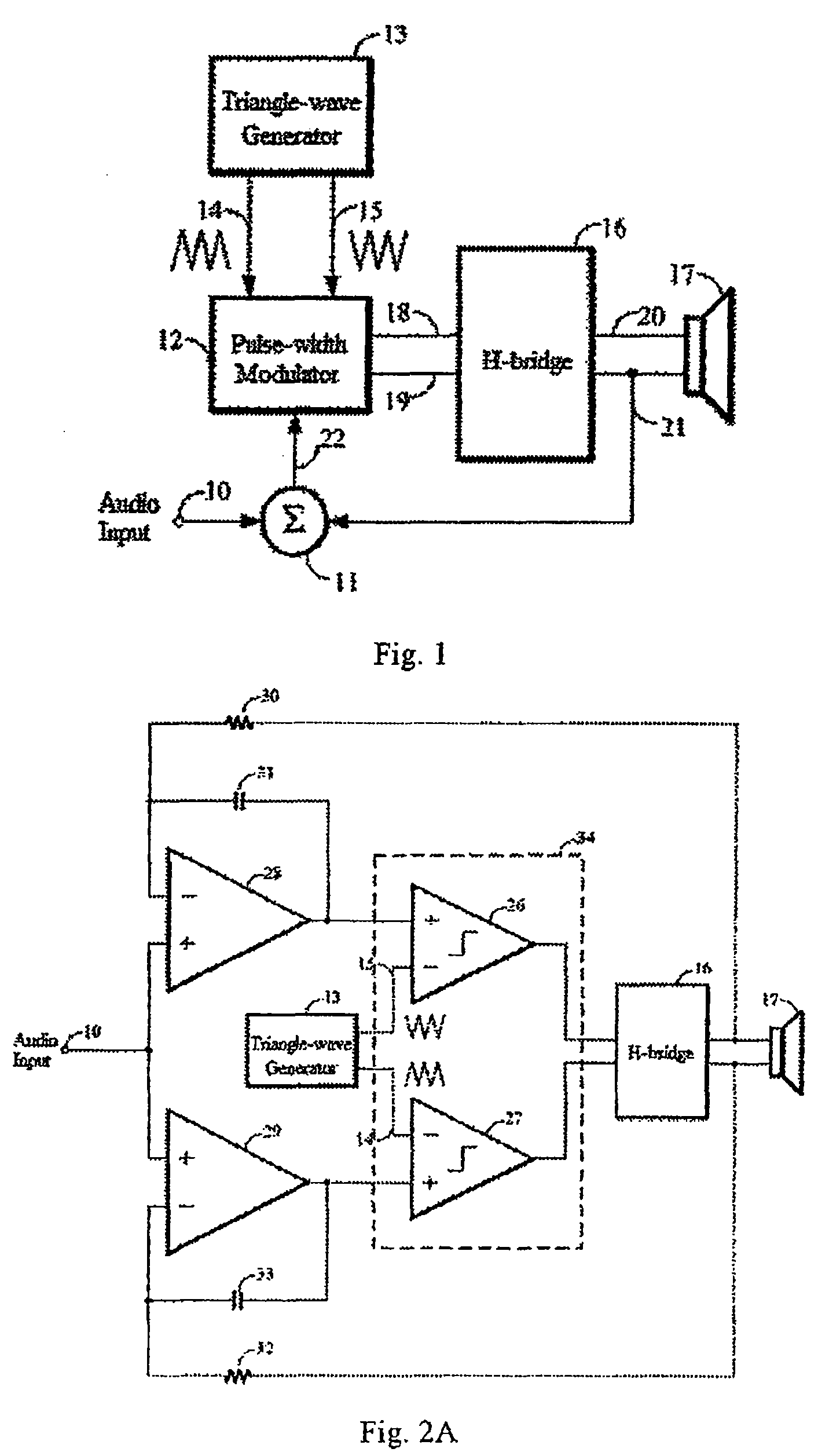
[0011]The object of the present invention is to provide a switching amplifier with higher performance and its modulation process to remove the aforesaid defects of the distortion in the prior art, and to make said switching amplifier with better performance of total harmonic distortion.
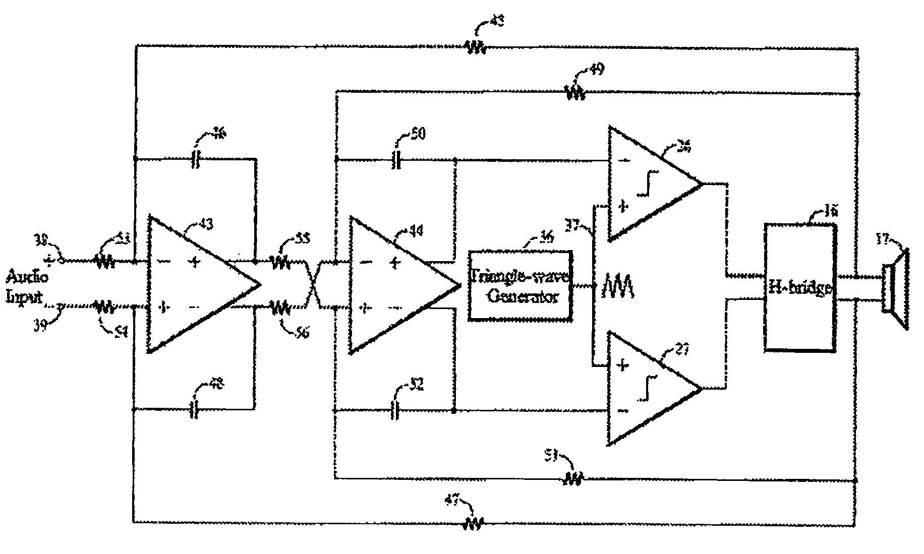
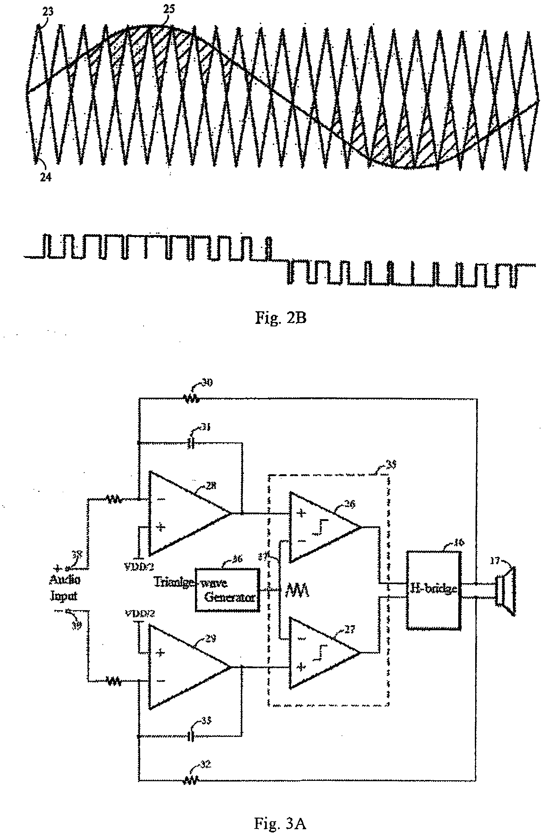
[0028]Compared with the prior art, the present invention provides a circuit and process of a switching amplifier with multiple-loop feedback and dual comparator pulse-width modulation. It has the characteristics such as compactor structure, lower total harmonic distortion, etc. The dual comparator PWM techniques can make the load to generate output three-level pulses without the use of output filters. Meanwhile, the adopted multiple-loop feedback can make the distortion of this switching amplifier to be the lowest. The present optimized circuit and process can make the switching amplifiers work without any extra low-pass filters in the feedback path, and hence to keep the effectively low-cost of the products.

Problems solved by technology

However, these output filters will increase the cost and size of the system.
This has detrimental effects on the portable application.
Although the switching amplifier with dual comparator modulation, in the prior art, has more advantages over the traditional switching amplifier with single comparator modulation, the degree of distortion is still unsatisfying due to the non-linear characteristic of the power switching, which limits its advanced applications.

Method used


Image

  • Switching amplifier and its modulation process
  • Switching amplifier and its modulation process
  • Switching amplifier and its modulation process

Examples


Embodiment Construction

[0037]The embodiments of the invention will be described in detail by referring to the figures as follows. It should be noted that the figures are used only for the readers to understand easily the embodiments of the invention; they cannot be understood as the end description of the invention or the limitation on the scope of the Claims. Besides, the figures do not need to be drawn in proportion.

[0038]It should be point out firstly that the inventors get the conclusions from the experiments and theories, which comprise: one of the most important characteristics of the ‘negative feedback’ technique is to suppress the non-linear characteristic of the analog circuit, the more feedback loops, and the more powerful suppression to the distortion. Therefore, the multiple ‘feedback’ technique will be applied to the switching amplifier in the present invention by the integration of the experiments and theories, especially, to a PWM switching amplifier with dual comparator to get the better p...


PUM


Abstract

The present invention discloses a switching amplifier and its modulations process, which belongs to the field of non-filters-type switching amplifier. The switching amplifier comprises; pulse-width modulation with dual comparator, multiple-loop feedback structure, only one integrating amplifier with dual-ends output needed for each loop, no less than two feedback loops set between the integrating amplifier and H-bridge, in addition, no any low-pass filters needed adding to the feedback path. Multiple feedback loops are adopted in the present invention, which can low the distortion of the switching amplifier to the extent. Furthermore, no any extra low-pass filters are needed adding to the feedback path, which making the products a higher cost effectiveness.

Description

BACKGROUND OF THE INVENTION[0001]1. Field of the Invention[0002]The present invention relates to a switching amplifier and its modulation process, more particularly, it relates to a non-filter switching amplifier and its modulation process.[0003]2. Description of Prior Art[0004]A conventional pulse-width-modulation (PWM) D-type switching amplifiers with two level output needs output filters, which consisting of the extra inductor and capacitor generally, to reduce the electromagnetic interference (EMI). However, these output filters will increase the cost and size of the system. This has detrimental effects on the portable application.[0005]The dual comparator modulation with three level output is generated in the prior art to overcome this defect. Although the dual comparator modulation does not need any output filters, it can make utmost of all the four work states of the H-bridge. It can send the current to the load only in demand, and the transported current will be completely c...

Claims


Application Information

Patent Timeline
IPC IPC(8): H03F3/217H03F3/38
CPCH03F3/2173H03F1/32
Inventor CHENG, JIN
Owner APEXONE MICROELECTRONICS
Learn More