

Display device
a technology of a display device and a bending plate, which is applied in the direction of semiconductor devices, instruments, optics, etc., can solve the problems of reducing the display quality, affecting the display quality, and the deformation of the sealing member, so as to prevent any reduction in the display quality
- Summary
- Abstract
- Description
- Claims
- Application Information
AI Technical Summary
Benefits of technology
Problems solved by technology
Method used
Image

Examples
first preferred embodiment
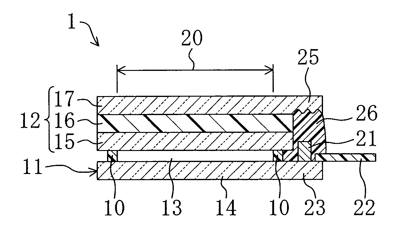
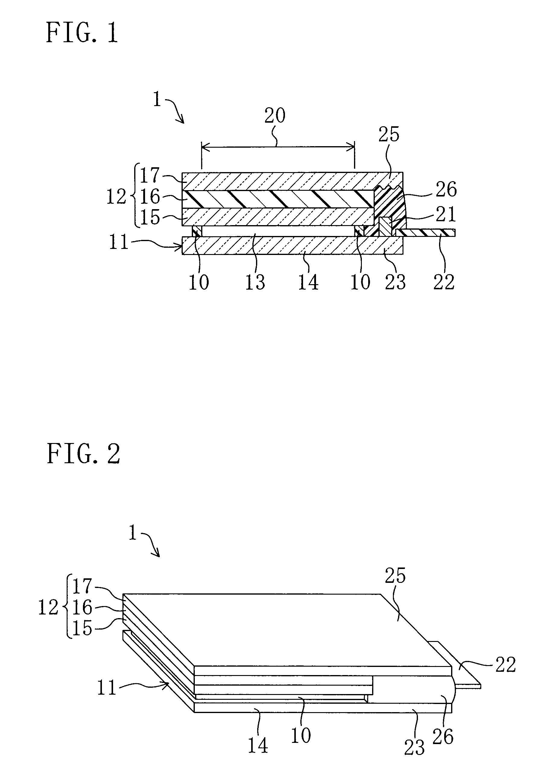
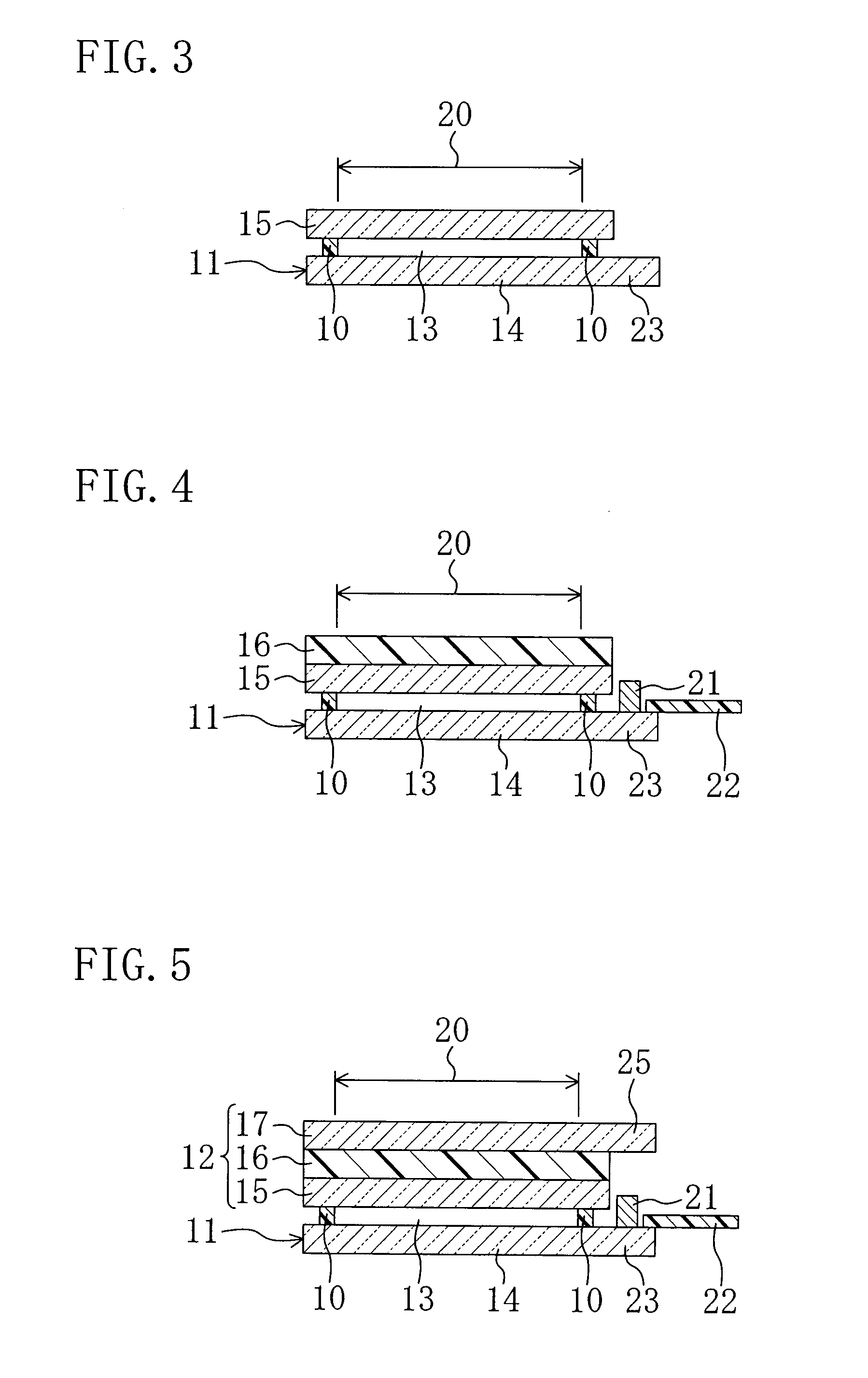
[0074]FIGS. 1 to 7 show a first preferred embodiment of the present invention. FIG. 1 is a sectional view illustrating the schematic structure of a liquid crystal display device 1, FIG. 2 is a perspective view of the liquid crystal display device 1 and FIGS. 3 to 7 are sectional views illustrating the steps of manufacturing the liquid crystal display device 1.
[0075]As shown in FIGS. 1 and 2, the liquid crystal display device 1 includes a flexible first substrate 11 on which TFTs (not shown) are formed as a plurality of switching elements, a second substrate 12 arranged to face the first substrate 11 and a liquid crystal layer 13 as a display medium layer provided between the first substrate 11 and the second substrate 12. Though not shown, a backlight unit as a light source is provided on the side of the first substrate 11 opposite the liquid crystal layer 13. The liquid crystal display device 1 preferably is a transmissive liquid crystal display device which performs transmissive d...
second preferred embodiment
[0098]FIGS. 8 and 9 show a second preferred embodiment of the present invention. FIG. 8 is a plan view illustrating a liquid crystal display device 1 from which a second substrate 12 is omitted and FIG. 9 is a sectional view illustrating the schematic structure of the liquid crystal display device 1. In the following preferred embodiments, the same components as those shown in FIGS. 1 to 7 are indicated by the same reference numerals to omit detailed explanation.
[0099]In the liquid crystal display device 1 of the present preferred embodiment, through holes 31 are formed in the extending region 25 and the mounting region 23 as shown in FIGS. 8 and 9 instead of roughening the surface of the extending region 25. The through holes 31 are formed in parts of the extending region 25 and the mounting region 23 in contact with the resin 26. According to the present preferred embodiment, two through holes 31 each having a circular or substantially circular section are formed at a certain inte...
third preferred embodiment
[0102]FIGS. 10 to 16 show a third preferred embodiment of the present invention. FIG. 10 is a sectional view illustrating the schematic structure of a liquid crystal display device 1, FIG. 11 is a perspective view illustrating the appearance of the liquid crystal display device 1 and FIGS. 12 to 16 are sectional views illustrating the steps of manufacturing the liquid crystal display device 1.
[0103]Different from the first preferred embodiment in which the extending region 25 consists of a portion of the transparent plate 17, the extending region 25 of the present preferred embodiment includes a portion of the polarizer 16. In general, the shape of the polarizer preferably is substantially the same as that of the plastic plate 15 of the second substrate 12. However, the polarizer 16 of the present preferred embodiment preferably is shaped substantially the same as the plastic plate 14 of the first substrate 11 and stacked on the plastic plate 15 of the second substrate 12 as shown i...
PUM
 Abstract
Description
Claims
Application Information