Balance spring, regulated balance wheel assembly and methods of manufacture thereof

Inactive Publication Date: 2009-05-07
CARBONTIME
View PDF34 Cites 37 Cited by
  • Summary
  • Abstract
  • Description
  • Claims
  • Application Information

AI Technical Summary

Benefits of technology

[0080]The outermost part (end plate) of the spring is also preferably formed integrally with the spring. The geometry of the outermost end as described below may differ from conventional spring ends. Conventionally the end of the spring is of small rectangular section and the long side of the rectangle cross section is parallel to the axis of rotation of the oscillator. In the present invention the geometry

Problems solved by technology

This technique is particularly but not exclusively suitable for ceramic or other material considered

Method used


Image

  • Balance spring, regulated balance wheel assembly and methods of manufacture thereof
  • Balance spring, regulated balance wheel assembly and methods of manufacture thereof
  • Balance spring, regulated balance wheel assembly and methods of manufacture thereof

Examples


Embodiment Construction

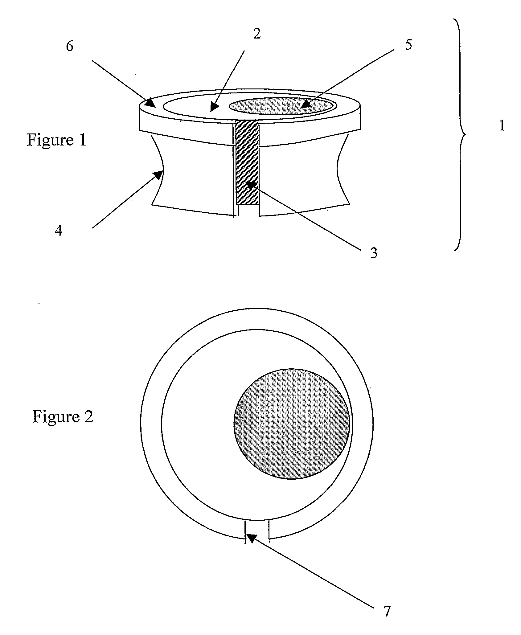
[0091]FIG. 1 shows a mass appendage assembly 1 that comprises a regulating element 2 mounted in a cylindrical setting 6. The inner surface of the setting 6 and the outer surface of the regulating element 2 are in threaded engagement. The setting 6 has a split 7 down one side parallel to its axis. The inner diameter of the setting 6 is smaller than the outer diameter of the regulating element 2 so that when the regulating element is screwed into engagement with the setting 6, the setting 6 expands and the size of the split 7 increases. The thread 3 on the outer surface of the regulating member can be seen in FIG. 1. The split 7 can be seen in FIG. 2. The side wall of the setting 6 has a recess 4 cut into it. The mass appendage assembly 1 is designed to be let into a through hole formed on a balance wheel in a contracted (e.g. cool) state. Upon returning to its normal state, the walls of the setting expand and fit against the inner walls of the through hole to secure the mass appendag...


PUM

PropertyMeasurementUnit
Massaaaaaaaaaa
Lengthaaaaaaaaaa
Flexibilityaaaaaaaaaa

Abstract

A balance spring comprising a flat spiral coil and a non-elastic inner attachment part formed by laser beam cutting. The spring has an outer attachment plate in the plane of the coil formed with a channel which receives and protects the outer winding of the coil. The outer attachment plate has a curved attachment edge which allows the location of the oscillator dead point to be varied without affecting spring frequency.

Description

FIELD OF THE INVENTION[0001]The present invention relates to refinements concerning balance wheel mass and timing appendages, and the shape of and processes for making balance springs previously introduced by the present inventor in WO 2004 / 008259 and WO 2005 / 040943.BACKGROUND OF THE INVENTION[0002]The balance wheel as is found in a horological mechanism or other precision instrument is required to oscillate isochronically providing the required inertia to the balance spring's restoring couple. For a given restoring couple of the balance spring the inertia of the balance may be found by adjusting the centre of its gyratory mass. This is the case in high quality time keepers which have a fixed active length of balance spring and therefore a fixed restoring couple at a given temperature.SUMMARY OF THE INVENTIONBalance Spring Manufacture[0003]In a first aspect, the present invention relates to refinements to the balance spring manufacturing process, particularly the forming and finishi...

Claims


Application Information

Patent Timeline
IPC IPC(8): G04B1/10B29C35/08
CPCF16F1/10F16F2226/00G04D3/0069G04B17/325G04D3/0041G04B17/066
Inventor LEVINGSTON, GIDEON
Owner CARBONTIME
Why Eureka
Try Eureka