
Communication quality measuring apparatus and communication quality measuring method

Inactive Publication Date: 2009-05-07
NEC CORP
View PDF10 Cites 79 Cited by
  • Summary
  • Abstract
  • Description
  • Claims
  • Application Information

AI Technical Summary

Benefits of technology

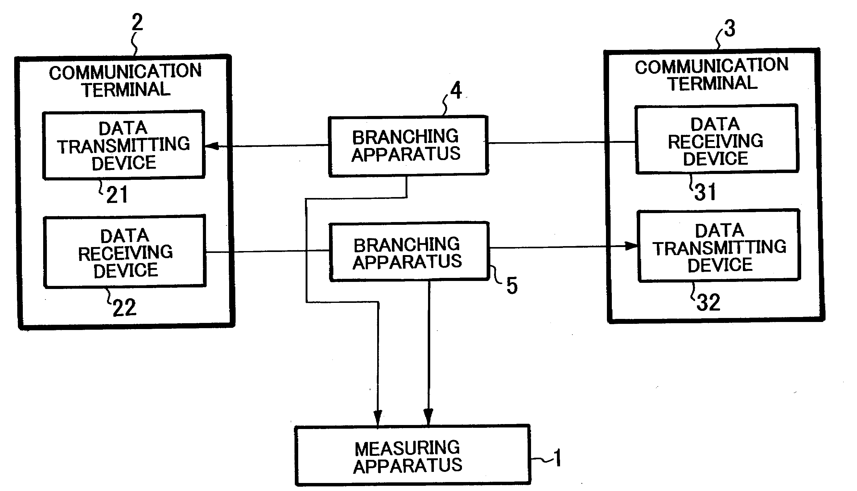
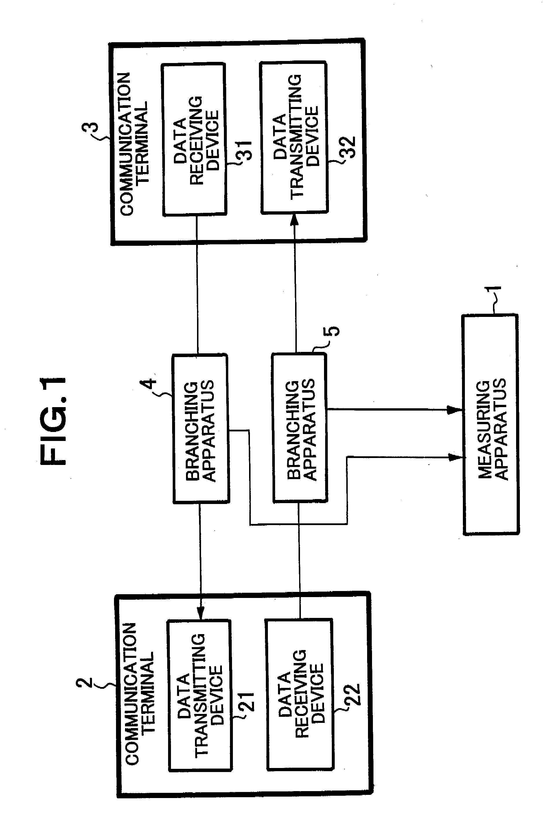
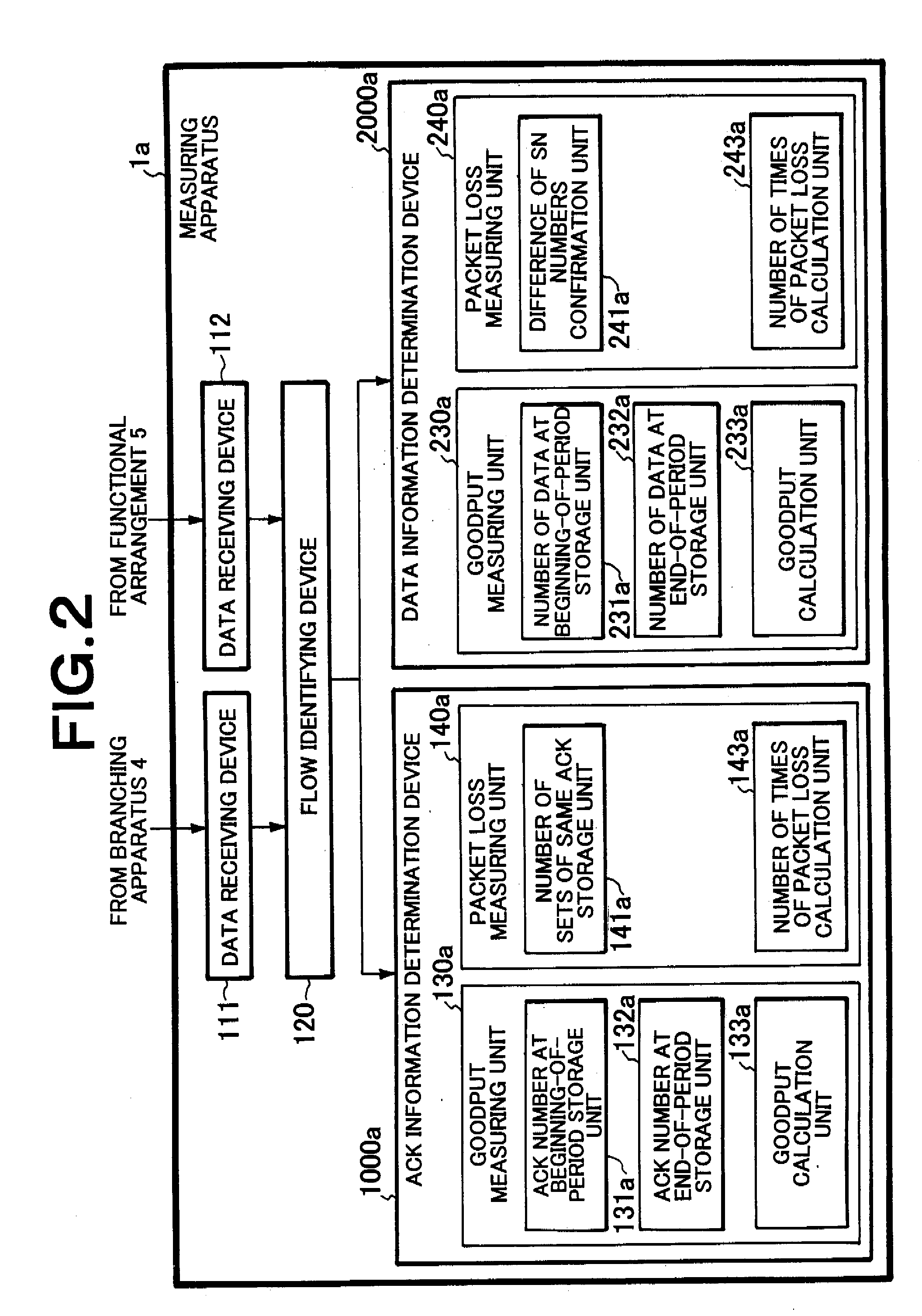
[0041]Accordingly, an object of the present invention, which was made in view of the above problems, + is to permit a measuring apparatus to measure quality of “throughput”, “goodput”, “packet loss”, and “RTT” between communication terminals with a low calculation capability. Further, an object of the present invention is to make it possible to measure quality even if all the packets cannot be obtained.
[0085]The present invention is a network quality measuring method of measuring quality of a network which is characterized by including a step of using the packets in a part of a certain period during which a reception confirmation signal is transmitted from a data reception side to a data transmission side as a target to be measured and calculating a number of times of a data loss, a data loss rate, a data loss time, and a data loss packet, which would be calculated when all the packets including the packets which cannot be measured in the certain period were obtained and calculated. Accordingly, even if a part of the packets are used as the target to be measured, the number of times of a data loss, the data loss rate, the data loss time, and the data loss packet can be accurately calculated.

Problems solved by technology

A first problem of the first method resides in that requires a sophisticated calculation capability to measure quality of a flow.
A second problem of the first method resides in that when all the packets of the flow to be measured cannot be obtained, quality cannot be correctly measured.
As a result, quality cannot be correctly counted.

Method used


Image

  • Communication quality measuring apparatus and communication quality measuring method
  • Communication quality measuring apparatus and communication quality measuring method
  • Communication quality measuring apparatus and communication quality measuring method

Examples


first embodiment

[0115]FIG. 4 is a block diagram showing an arrangement a measuring apparatus 1b according to the present invention.

[0116]The measuring apparatus 1b of the first embodiment is composed of a data receiving device 111 to which data is input from a branching apparatus 4, a data receiving device 112 to which data is input from a branching apparatus 5, a flow identifying device 120 for identifying the input data of each flow, a sampling device 170 for sampling input packets, an ACK information determination device 1000b for measuring quality only from ACK side information, a goodput calculation unit 130b in the ACK information determination device 1000a, a storage unit 131b for storing the final ACK number in an immediately previous monitor period, a storage unit 132b for storing the final ACK number of a monitor period, a goodput calculation unit 133b for calculating goodput from the contents stored in the storage units 131b and 132b, a packet loss calculation unit 140b, a number of the ...

second embodiment

[0149]FIG. 8 is a block diagram showing an arrangement a measuring apparatus 1c according to the present invention.

[0150]The measuring apparatus 1c of the second embodiment is composed of a data receiving device 111 to which data is input from a branching device 4, a data receiving device 112 to which data is input from a branching device 5, a flow identifying device 120 for identifying the input data of each flow, a sampling device 170 for sampling input packets, an ACK information determination device 1000c for measuring quality only from ACK side information, a goodput measuring unit 130a in the ACK information determination device 1000c, a storage unit 131b for storing the final ACK number in an immediately previous monitor period, a storage unit 132b for storing the final ACK number in a monitor period, a goodput calculation unit 133b for calculating goodput from the contents stored in the storage units 131b and 132b, a packet loss measuring unit 140c, an ACK number differentia...

third embodiment

[0180]FIG. 10 is a block diagram showing an arrangement a measuring apparatus 1d according to the present invention.

[0181]The measuring apparatus 1d of the third embodiment is composed of a data receiving device 111 to which data is input from a branching device 4, a data receiving device 112 to which data is input from a branching device 5, a flow identifying device 120 for identifying the input data of each flow, a sampling device 170 for sampling input packets, an SN information determination device 2000d for measuring quality only from SN side information, a goodput calculation unit 230d in the SN information determination device 2000d, a goodput calculating unit 230d in the SN information determination device 2000d, a storage unit 232a for storing the final SN number in an immediately previous monitor period, a storage unit 231d for storing the final SN number in a monitor period, a goodput calculation unit 233d for calculating goodput from the contents stored in the storage un...


PUM


Abstract

A measuring apparatus for measuring quality of a network accurately measures a number of times of a data loss even if all the packets to be measured are not obtained or cannot be obtained. Further, a process load applied to the measuring apparatus is decreased by processing a part of the packets to be measured.The measuring apparatus, which measures quality of a network, includes a means for estimating a sampling rate from a number showing sequences stored in packets and a number of received data and a means for estimating a data loss, which would be measured when all the packets were obtained, from a result of sampling measurement by carrying out a differential process and a statistical process using the sequences in the packets, thereby the measuring apparatus measures a number of times of the data loss in the sampling measurement.

Description

TECHNICAL FIELD[0001]The present invention relates to a communication quality measuring apparatus for and a communication quality measuring method of measuring communication quality of a network.BACKGROUND ART[0002]Quality of a network processed by the present invention means quality of a packet input to a measuring apparatus. A packet is input to the measuring apparatus from a branching apparatus interposed between communication terminals. Further, quality of a packet means throughput, goodput, a packet loss, and RTT (Round Trip Time).[0003]An apparatus for measuring quality of a network will be explained below using TCP (Transmission Control Protocol) as an example for simplification.[0004]Patent Document 1 will be explained here.[0005]A method of measuring goodput and packet loss disclosed in Patent Document 1 will be explained using FIGS. 1, 2, and 3.[0006]FIG. 1 is a view showing a scope to which Patent Document 1 is applied, FIG. 2 is a block diagram of Patent Document 1, and ...

Claims


Application Information

Patent Timeline
IPC IPC(8): G06F11/30H04L69/40
CPCH04L1/1867H04L43/0829H04L43/024H04L1/20
Inventor YAMASAKI, YASUHIRO
Owner NEC CORP
Learn More