Gas sensor

a technology of gas sensor and sensor body, which is applied in the direction of liquid/fluent solid measurement, material electrochemical variables, instruments, etc., can solve the problems of difficult to sufficiently reduce the difference in sintering shrinkage, the element of gas sensor may be subject to cracking or breakage, and the restriction of changing materials, etc., to achieve efficient heating

Active Publication Date: 2009-05-07
NGK SPARK PLUG CO LTD
View PDF13 Cites 18 Cited by
  • Summary
  • Abstract
  • Description
  • Claims
  • Application Information

AI Technical Summary

Benefits of technology

[0011]The present invention was made in consideration of the above problems of the prior art, and an object thereof is to provide a gas sensor having high reliability, in which the detection element is subject to less warping.

Problems solved by technology

If the gas sensor element becomes warped, the gas sensor element may be subject to cracking or breakage.
However, taking the performance, strength and durability of the gas sensor element into consideration, there is a restriction in changing the materials.
Heretofore, it has been difficult to sufficiently reduce the difference in sintering shrinkage so as to prevent warping while still maintaining good sensor performance and physical characteristics.

Method used


Image

  • Gas sensor
  • Gas sensor
  • Gas sensor

Examples


embodiment 1

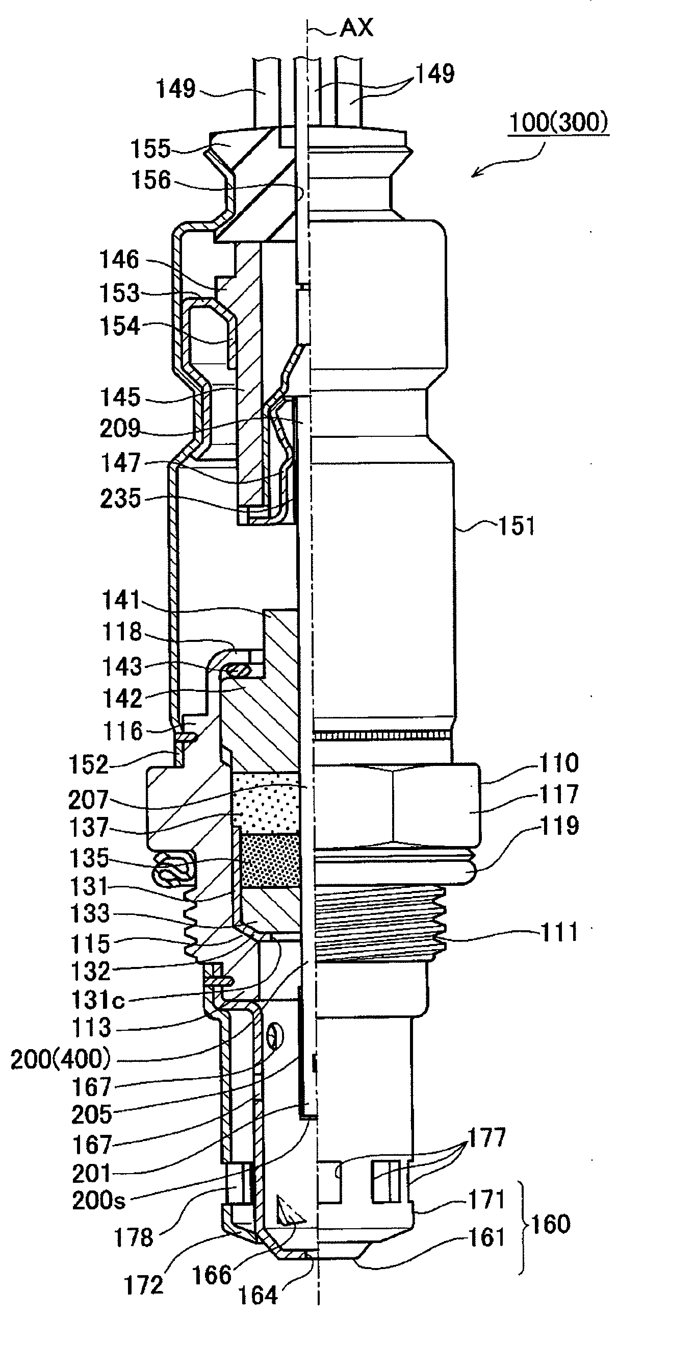
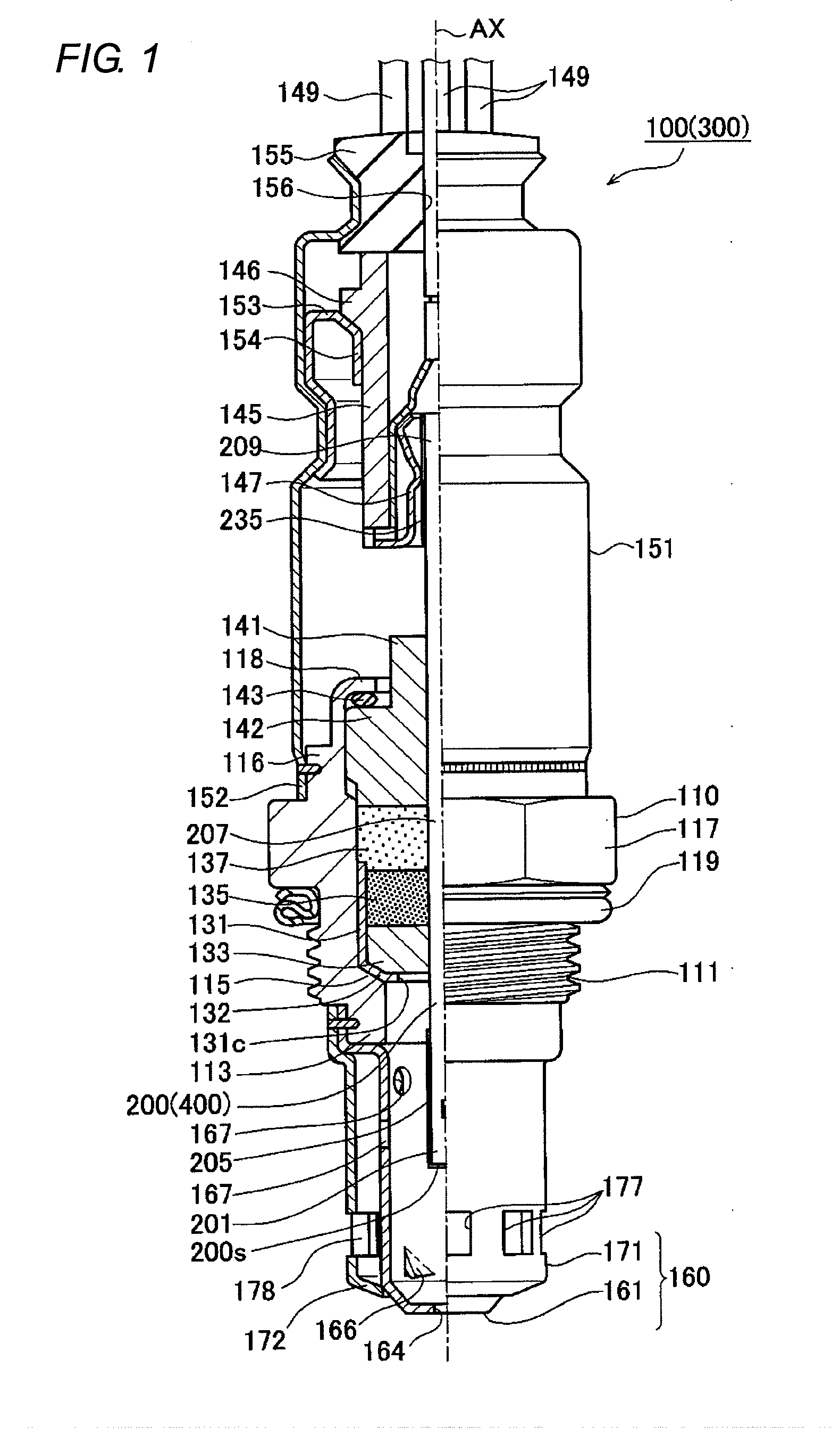
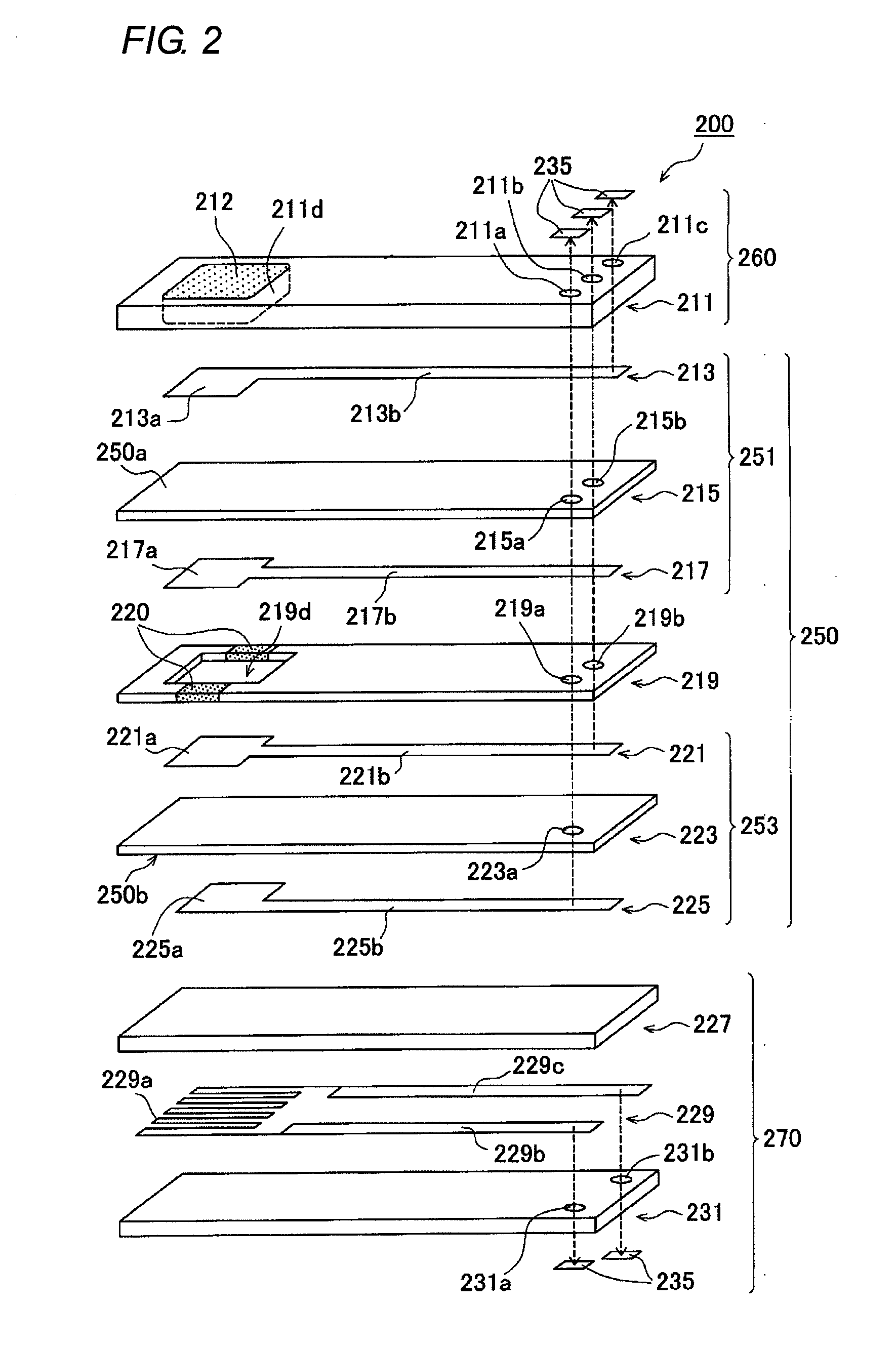
[0036]Hereinafter, a description is given of an embodiment of the present invention with reference to the drawings. FIG. 1 shows a gas sensor 100 according to Embodiment 1. Also, FIG. 2 is a disassembled perspective view showing a detection element 200 of the gas sensor 100. Further, FIG. 3 and FIG. 4 are cross-sectional views showing the leading end side portion and the base end side portion of the detection element 200, respectively. Also, in FIG. 1, the lower side of the drawing is the leading end side in the axial line AX direction (hereinafter also called a “leading end side”), and the upper side of the drawing is the base end side in the axial line AX direction (hereinafter simply called a “base end side”). Further, in FIG. 2, the left side of the drawing is the leading end side, and the right side of the drawing is the base end side.

[0037]The embodiment shows, as an example of the gas sensor 100, a full-range air-fuel ratio sensor attachable to an exhaust pipe of an automobil...

embodiment 2

[0091]Next, a description is given of Embodiment 2. FIG. 5 is a disassembled perspective view of a detection element 400 that includes a gas sensor 300 according to the above aspects of the present invention. Further, FIGS. 6 and 7 are cross-sectional views showing the leading end side portion and the base end side of the detection element 400, respectively. In the gas sensor 300 according to the present embodiment, the mode of the detection element 400 is different from the mode of the detection element 200 of the gas sensor 100 according to Embodiment 1. Other features are basically similar to those of Embodiment 1 described above. Descriptions of parts that are similar to those of Embodiment 1 are omitted or simplified.

[0092]The detection element 400 according to Embodiment 2 is formed by simultaneously sintering a plurality of mutually stacked layers containing different main components, and has a plate shape (that is, a plate strip) extending in the axial line AX direction. The...

embodiment 3

[0117]Next, a description is given of Embodiment 3. FIG. 8 is a disassembled perspective view showing a detection element 600 of a gas sensor according to Embodiment 3. Further, FIG. 9 is a cross-sectional view showing the leading end side portion of the detection element 600. In the gas sensor according to Embodiment 3, the mode of the detection element 600 differs from that of the detection element 200 of the gas sensor 100 according to Embodiment 1. Other features are basically similar to those of Embodiment 1 described above, and descriptions of portions similar to those of Embodiment 1 are omitted or simplified.

[0118]The detection element 600 according to Embodiment 3 is formed by simultaneously sintering a plurality of mutually stacked layers containing different main components, and has a plate shape (that is, plate strip) extending in the axial line AX direction. The detection element 600 includes a sensing portion 650, a porous layer 612, a shielding layer 610, an introduct...


PUM

PropertyMeasurementUnit
wt %aaaaaaaaaa
thickness t01aaaaaaaaaa
thickness t02aaaaaaaaaa

Abstract

A gas sensor including a detection element having a stacked structure configured to detect a specified gas component contained in a gas to be detected. The detection element includes: a sensing portion including one or more solid electrolyte layers containing a first material as a main component and having a first surface and a second surface opposite the first surface; a first portion stacked on the first surface and including one or more first base layers containing a second material as a main component different from the first material; and a second portion stacked on the second surface and including one or more second base layers containing the second material. A total thickness of the one or more second base layers in a stacking direction is not less than 80% but not more than 120% of a total thickness of the one or more first base layers.

Description

BACKGROUND OF THE INVENTION[0001]1. Field of the Invention[0002]The present invention relates to a gas sensor including a detection element configured to detect a specified gas component contained in a gas to be detected. An example of the gas sensor is one having a stacked detection element made by simultaneously sintering a plurality of stacked layers which contain different main components.[0003]2. Description of the Related Art[0004]The use of a gas sensor attached to an exhaust pipe of an automobile and including a detection element configured to vary an electromotive force or a resistance value according to the concentration of a specified component (for example, nitrogen oxide, oxygen, etc.) of exhaust gas is known. A stacked detection element manufactured by simultaneously sintering a plurality of stacked layers having different main components is also known. If the detection element is formed by simultaneous sintering, the sintering process is completed at one time, and a l...

Claims


Application Information

Patent Timeline
Patent Type & Authority Applications(United States)
IPC IPC(8): G01N27/406
CPCG01N27/4071
Inventor FURUTA, NOBUOMORI, SHIGEKI
Owner NGK SPARK PLUG CO LTD
Why Eureka
Try Eureka