Method for treating substrate and recording medium

a recording medium and substrate technology, applied in the direction of coatings, metallic material coating processes, chemical vapor deposition coatings, etc., can solve the problems of poor quality, contamination of film, generation of particles, etc., and achieve the effect of increasing productivity, efficient and clean inside maintenan

Inactive Publication Date: 2009-05-07
TOKYO ELECTRON LTD
View PDF1 Cites 103 Cited by
  • Summary
  • Abstract
  • Description
  • Claims
  • Application Information

AI Technical Summary

Benefits of technology

[0011]In accordance with the present invention, it is possible to provide a substrate processing method which is capable of efficiently and cleanly maintaining the inside of a p

Problems solved by technology

Upon repetition of the film formation by the film forming apparatus, the thickness of deposits increases, and finally the deposits are peeled off, thereby causing generation of pa

Method used


Image

  • Method for treating substrate and recording medium
  • Method for treating substrate and recording medium
  • Method for treating substrate and recording medium

Examples


first embodiment

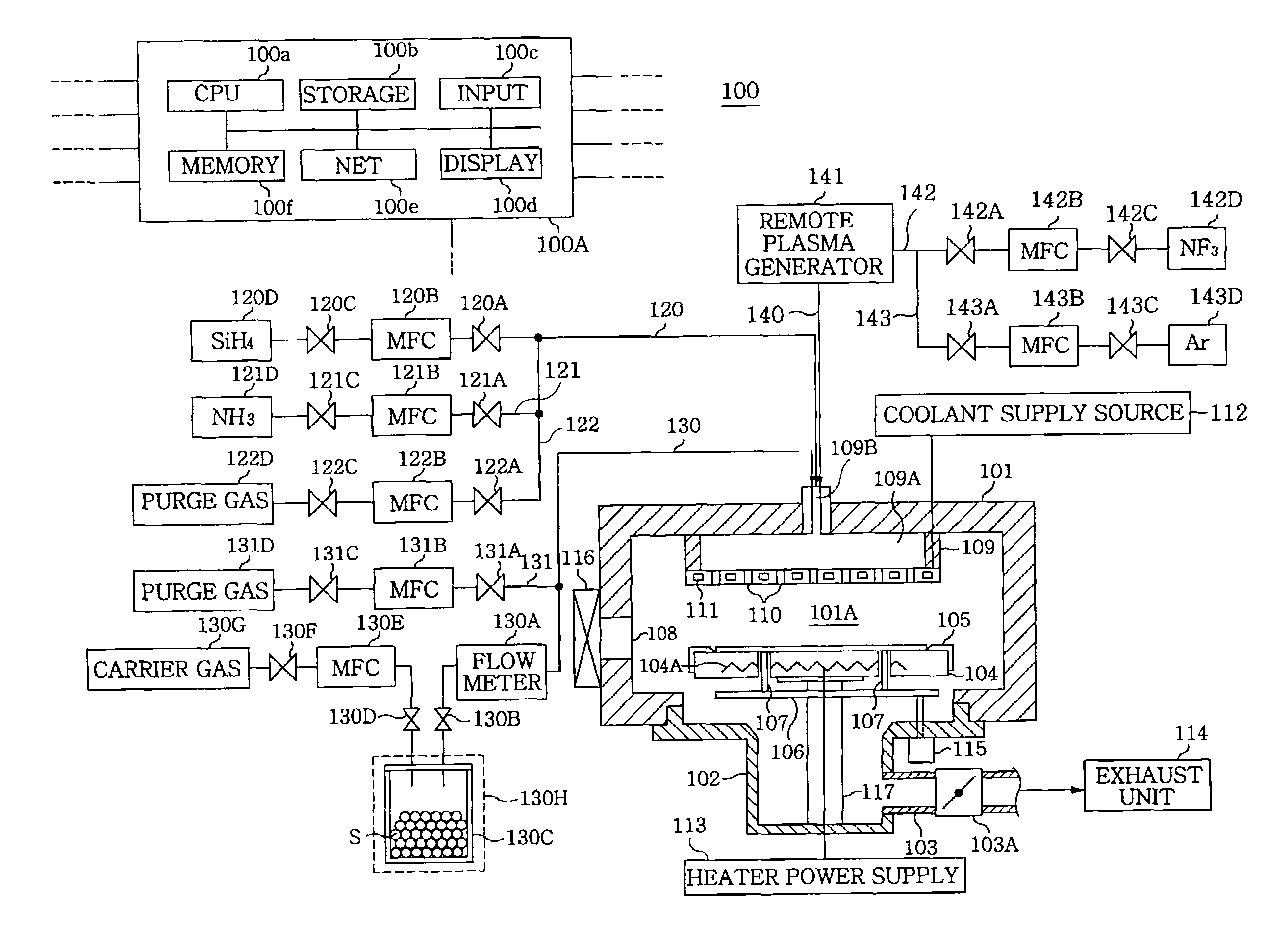
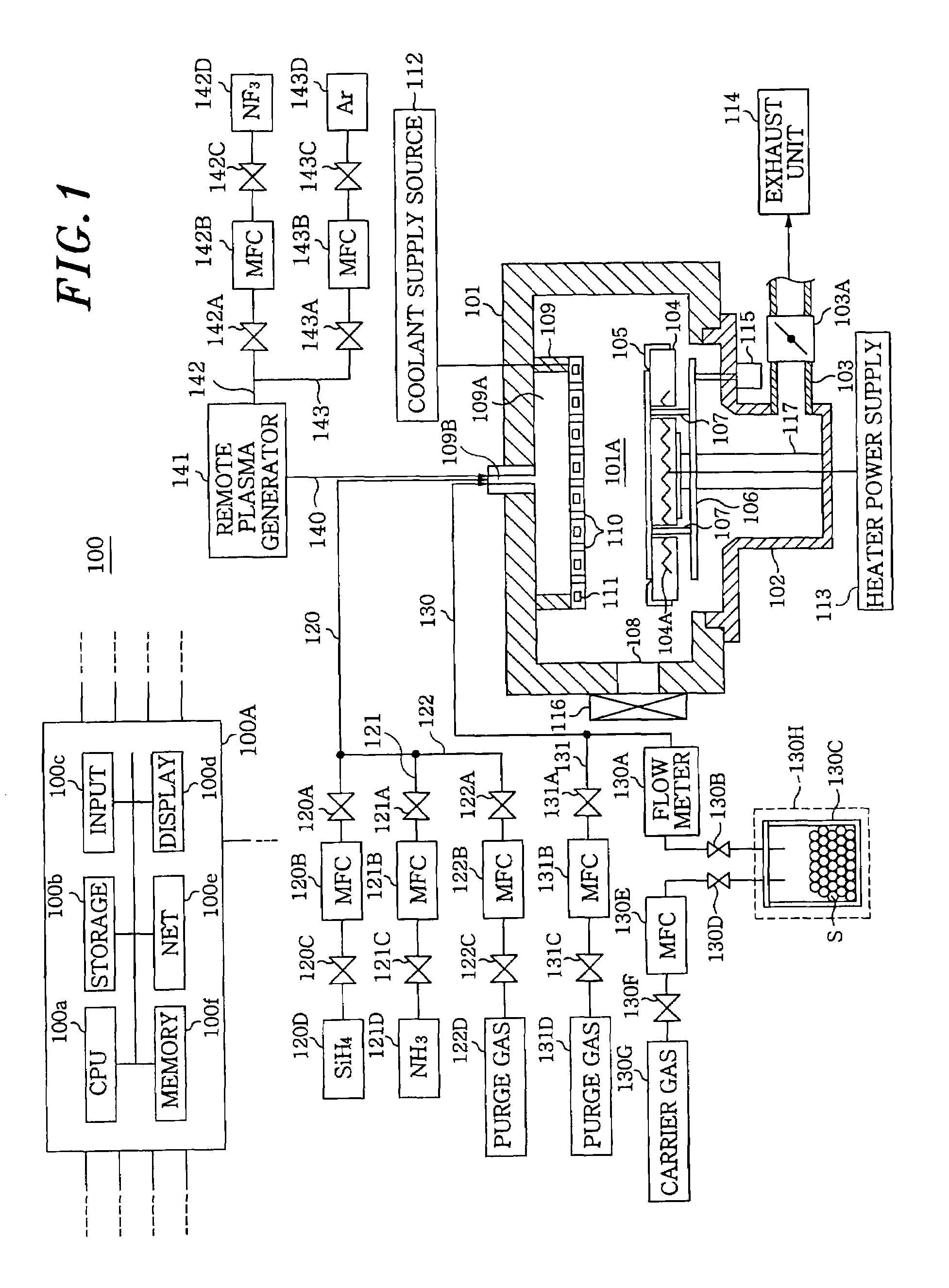
[0030]FIG. 1 is a schematic diagram showing a film forming apparatus 100 for performing a substrate processing method in accordance with a first embodiment of the present invention. Referring to FIG. 1, the film forming apparatus 100 includes a processing chamber 101 of a housing shape provided with an opening formed in its bottom, another processing chamber 102 connected with the opening and having a cylindrical part protruded downward, and an inner space 101A defined by the processing chambers 101 and 102. For example, the processing chambers 101 and 102 are formed of aluminum, or a metal material including aluminum such as aluminum alloy.

[0031]The inner space 101A can be exhausted through a gas exhaust port 103 provided to the processing chamber 102 to be in a depressurized state by, e.g., a gas exhaust unit 114 such as a vacuum pump or the like. Further, a pressure control valve 103A is installed in the gas exhaust port 103 to control a pressure in the inner space 101A.

[0032]Fur...

second embodiment

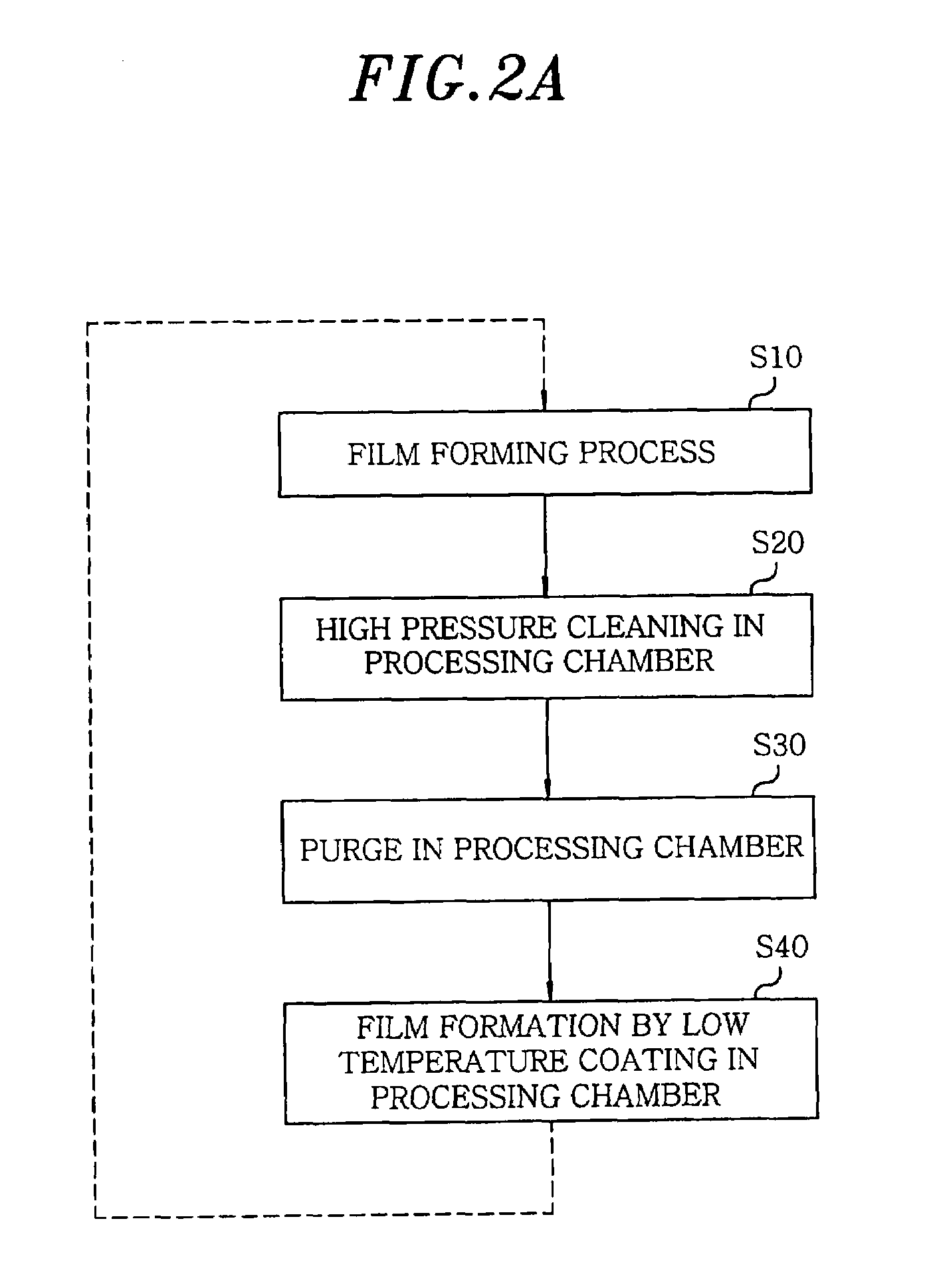
[0112]Hereinafter, an example of a substrate processing method using the film forming apparatus 100 is described on the basis of the above-mentioned substrate processing method. The substrate processing was performed based on the substrate processing method shown in FIG. 2A in the following example.

[0113]First, the process in step 10 was performed as follows. The temperature of the substrate supporting table 104 was set to be 672° C., and a substrate (300 mm wafer) was loaded into the inner space 101A by using, e.g., a transfer robot or the like.

[0114]Next, W(CO)6 maintained in the raw material supply unit 130C was sublimated to be a material gas and then supplied into the inner space 101A from the shower head 109 via the gas line 130, together with a carrier gas, e.g., Ar of which flow rate was 90 sccm and a diluent gas (purge gas), e.g., Ar of which flow rate was 700 sccm. In this case, the pressure in the inner space 101A was 20 Pa (0.15 Torr). As a result, the material gas was d...

third embodiment

[0121]Hereinafter, an example of a substrate processing based on the substrate processing method shown in FIG. 2B.

[0122]First, the process in step 10 was performed as follows. The temperature of the substrate supporting table 104 was set to be 600° C., and a substrate (300 mm wafer) was loaded into the inner space 101A by using, e.g., the transfer robot or the like.

[0123]Next, Ta(Nt-Am) (NMe2)3 maintained at 46° C. in the raw material supply unit was sublimated to be a material gas, and the material gas is supplied into the inner space 101A from the shower head 109 via the gas line 130, together with a carrier gas, e.g., Ar of which flow rate was 40 sccm. In this case, a diluent gas (purge gas), e.g., Ar, SiH4, and NH3 were also supplied into the inner space 101A from the shower head 109 via the gas line 120 at flow rates of 40 sccm, 500 sccm and 200 sccm, respectively.

[0124]In this case, the pressure in the inner pressure 101A was 40 Pa (0.3 Torr) . As a result, the material gas wa...


PUM

PropertyMeasurementUnit
Temperatureaaaaaaaaaa

Abstract

A method for processing a substrate includes a film forming step of supplying a film forming gas into the processing chamber to form a film on the substrate, a cleaning step of supplying a plasma-exited cleaning gas into the processing chamber after the film forming step to clean the inside of the processing chamber, and a coating step of forming a coating within the processing chamber after the cleaning step. The cleaning step includes a high pressure cleaning of regulating the pressure in the processing chamber so that cleaning is mainly performed by molecules formed by recombining radicals in the cleaning gas, and the coating step includes a low temperature film forming step of forming the coating film under the condition that the temperature of a substrate supporting table is set lower than that in the film formation on the substrate during the film formation step.

Description

FIELD OF THE INVENTION[0001]The present invention relates to a substrate processing method of a film forming apparatus for forming a film on a substrate to be processed, and a storage medium for storing a program for executing the substrate processing method on a computer.BACKGROUND OF THE INVENTION[0002]In a film forming apparatus for forming a film on a substrate to be processed such as a chemical vapor deposition (CVD) apparatus, the substrate is mounted in a processing chamber and a specific film formation is performed on the substrate. However, in the film formation process, while a desired thin film is formed on the substrate, a thin film is also attached and deposited to an inner wall of the processing chamber, a substrate supporting table and the like. Upon repetition of the film formation by the film forming apparatus, the thickness of deposits increases, and finally the deposits are peeled off, thereby causing generation of particles.[0003]Therefore, in order to remove the...

Claims


Application Information

Patent Timeline
IPC IPC(8): C23C16/02
CPCC23C16/0227C23C16/4405C23C16/34C23C16/16H01L21/304
Inventor YAMASAKI, HIDEAKINAKAMURA, KAZUHITOKAWANO, YUMIKO
Owner TOKYO ELECTRON LTD
Why Eureka
Try Eureka