Dual direction exercise treadmill for simulating a dragging or pulling action with a user adjustable constant static weight resistance

Inactive Publication Date: 2009-05-07
FITNESS TOOLS
View PDF24 Cites 20 Cited by
  • Summary
  • Abstract
  • Description
  • Claims
  • Application Information

AI Technical Summary

Benefits of technology

[0023]Generally speaking, the internal mechanical components of the treadmill are similar to (or can be similar to or the same as) the internal mechanical components of known treadmills. The treadmill comprises an endless belt looped about rollers or pulleys so as to provide a platform on which the user can stand, walk and / or run. A deck below a portion of the belt supports the belt and the user. A belt motor cooperates with the belt and / or the rollers or pulleys to move the belt, thus creating a moving platform on which the user can walk or run for the exercise regimen. An incline motor cooperates with the platform, the deck, the rollers or pulleys or rear legs to incline the belt to simulate a hill.

Problems solved by technology

However, with the exception of this inventor's inventions, this inventor is unaware of any specific exercise treadmill that is structured to allow the user to comfortably simulate a dragging or pulling motion; that is, a backwards walking motion either on a level plane or uphill.

Method used


Image

  • Dual direction exercise treadmill for simulating a dragging or pulling action with a user adjustable constant static weight resistance
  • Dual direction exercise treadmill for simulating a dragging or pulling action with a user adjustable constant static weight resistance
  • Dual direction exercise treadmill for simulating a dragging or pulling action with a user adjustable constant static weight resistance

Examples


first embodiment

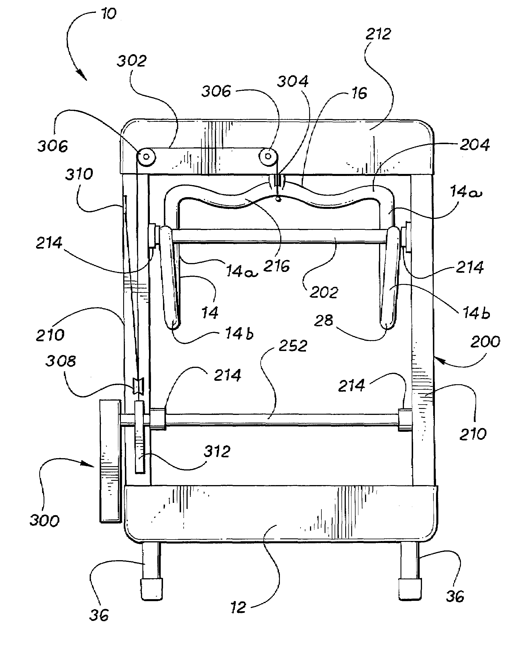
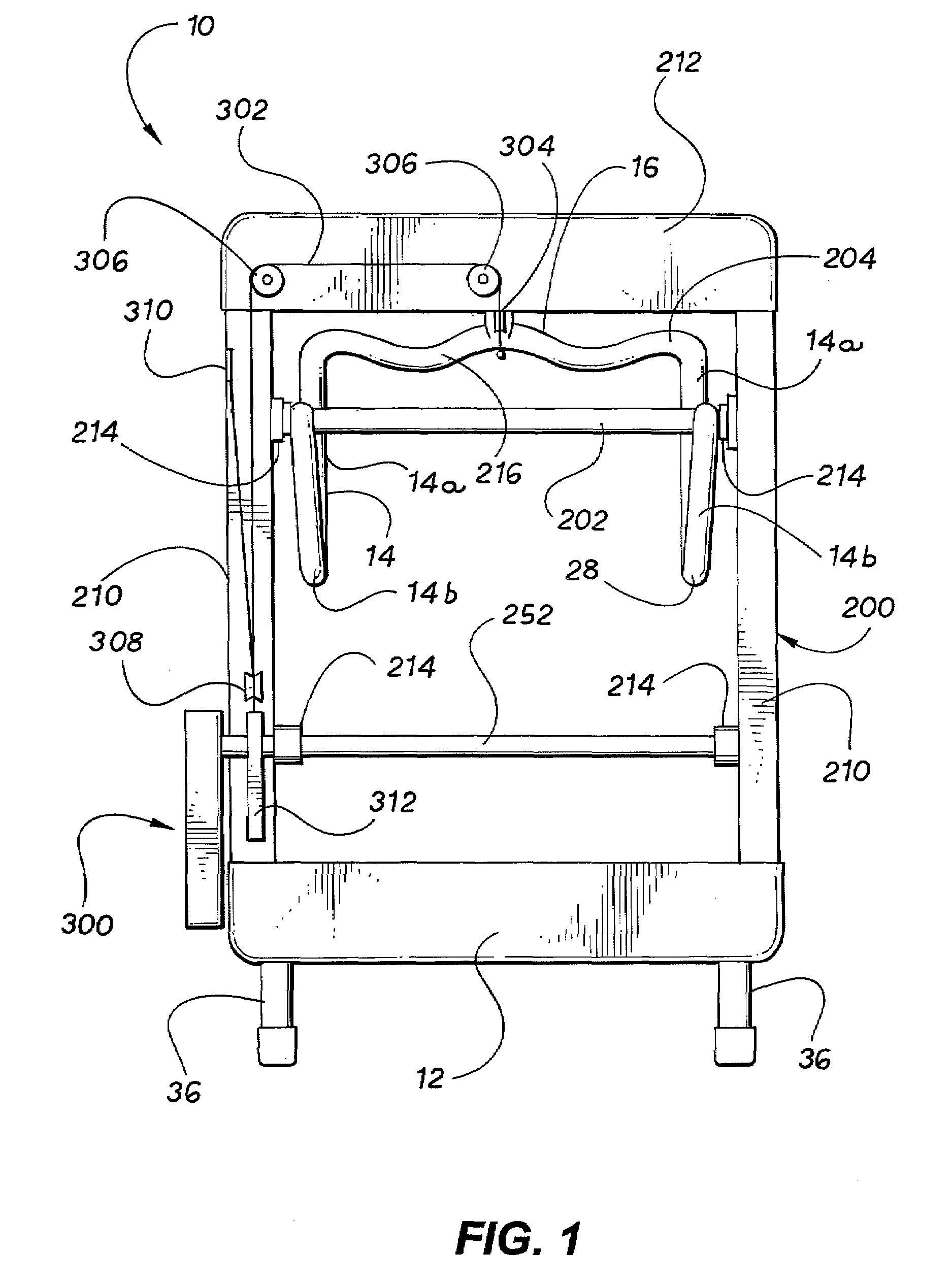
[0045]Referring now to the appended figures, the invention will be described in connection with representative preferred embodiments. FIG. 1 is a front view of the invention. FIG. 2 is a side view of the invention operating in reverse dragging / pulling mode in a level position, showing the moment arm weight resistance mechanism and a three-section resistance arm.

second embodiment

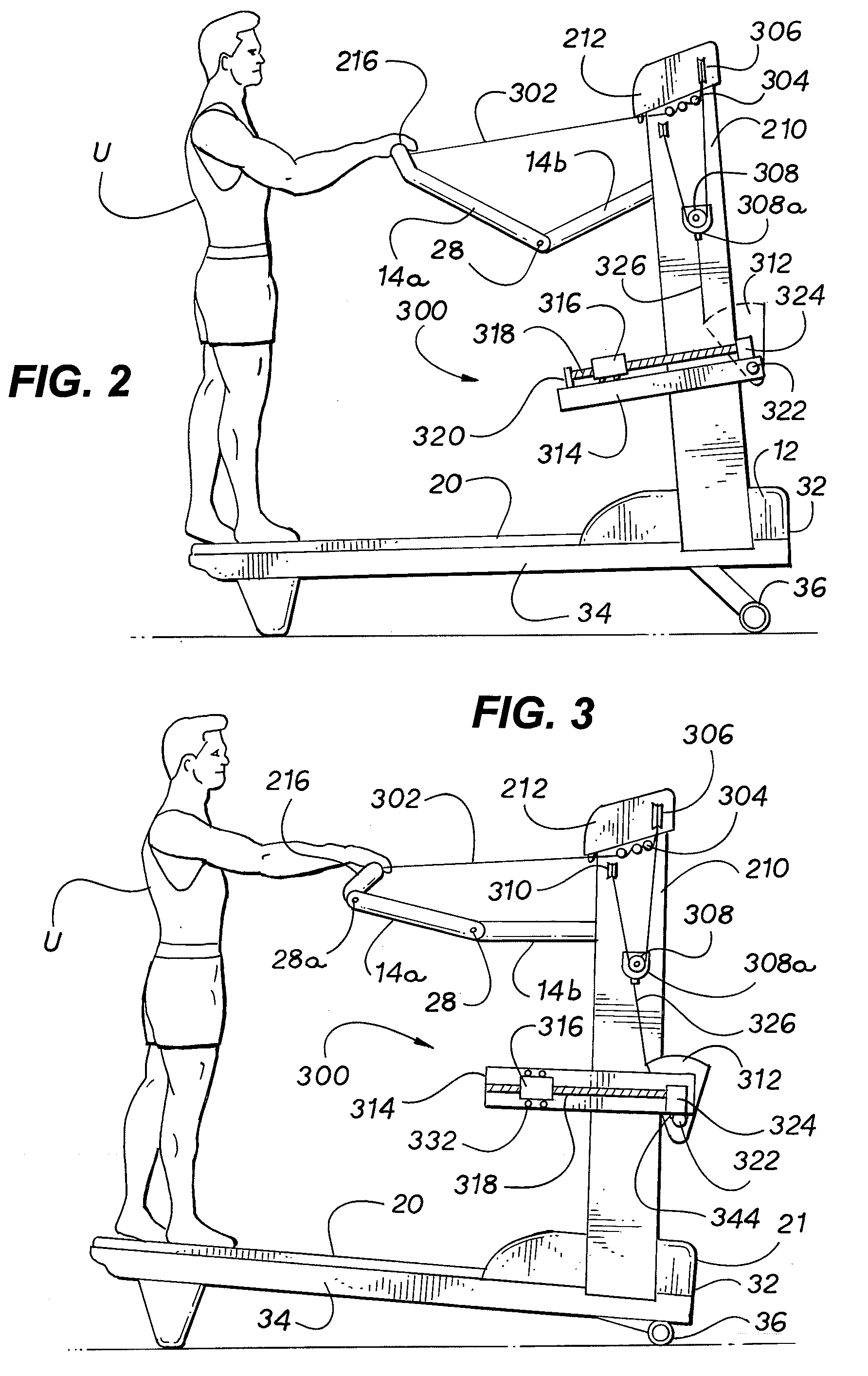
[0046]FIG. 3 is a side view of the invention operating in reverse dragging / pulling mode in an inclined position, showing the moment arm weight resistance mechanism and a five-section resistance arm. FIG. 4 is a side view of the invention operating in forward walking / running mode.

[0047]FIG. 5 is a side view of the moment arm weight resistance mechanism in the resting position. FIG. 6 is a side view of the moment arm weight resistance mechanism in a resistance position. FIG. 7 is a top view of an embodiment of the moment arm weight resistance mechanism of the invention. FIG. 8 is a side view of the embodiment of the moment arm weight resistance mechanism shown in FIG. 7. FIG. 9 is a side view of an alternate embodiment of the moment arm weight resistance mechanism of the invention. FIG. 10 is a sectional side view of the second embodiment of the moment arm weight resistance mechanism shown in FIG. 3 in larger detail.

[0048]FIG. 11 is a sectional side view of a representative weight and...


PUM


Abstract

An exercise treadmill having an endless moveable surface looped around rollers or pulleys to form an upper run and a lower run, the movable surface being rotated when one of the rollers or pulleys is rotated, and an exercise surface for walking or running while exercising, a weight resistance mechanism for providing a weight resistance for simulating the dragging or pulling of a load, wherein the weight resistance can be adjusted and set to a specific weight resistance setting; a movable hand controller operatively attached to the weight resistance mechanism for operating and controlling the exercise treadmill and the weight resistance mechanism, wherein the endless movable surface moves in a direction simulating walking or running backwards, and wherein the weight resistance mechanism applies a constant and static force to the hand controller generally only in the same as the direction the endless movable surface moves and opposite a pulling direction, whereby operation of the treadmill simulates the dragging or pulling of a load by a combination of the actuation of the weight resistance mechanism to simulate the load and the walking or running backwards to provide the dragging or pulling action.

Description

BACKGROUND OF THE INVENTION[0001]1. Technical Field[0002]This invention relates to the general technical field of exercise, physical fitness and physical therapy equipment and machines and to the more specific technical field of treadmills that can be operated in a rearward walking and running mode to simulate a reverse dragging and pulling exercise. This invention also relates to the more specific technical field of using a weight resistance mechanism to generate a constant static weight resistance for simulating the dragging and pulling of a load, which weight resistance can be adjusted (increased and decreased) while exercising.[0003]2. Prior Art[0004]Exercise, physical fitness and physical therapy equipment and machines are available in various configurations and for various purposes, and are available for all of the major muscle groups. The majority of such equipment and machines, especially in the exercise field, concentrate either on an aerobic or anaerobic workout or on area...

Claims


Application Information

Patent Timeline
Patent Type & Authority Applications(United States)
IPC IPC(8): A63B22/02
CPCA63B21/00076A63B2022/0292A63B21/1469A63B21/1484A63B21/1492A63B21/155A63B21/156A63B22/001A63B22/0023A63B22/02A63B22/0235A63B22/0242A63B23/047A63B2021/0616A63B2021/0617A63B21/0615A63B21/4043A63B21/4035A63B22/0292A63B21/0617A63B21/0616A63B21/4047
Inventor ELLIS, JOSEPH K.
Owner FITNESS TOOLS
Why Eureka
Try Eureka