Vibration damper and method for the production of a three-pipe system for a vibration damper

a technology of vibration damper and three-pipe system, which is applied in the direction of vibration dampers, mechanical equipment, resilient suspensions, etc., can solve the problems of increasing scrap, complicated assembly of valve modules, and different parts having to be sealed, and achieves the effect of easy production

Inactive Publication Date: 2009-05-14
THYSSENKRUPP BILSTEIN
View PDF23 Cites 32 Cited by
  • Summary
  • Abstract
  • Description
  • Claims
  • Application Information

AI Technical Summary

Benefits of technology

[0008]Against this background, it is an object of the invention to provide a vibration damper having a three-pipe system, which damper is easy to produce.
[0009]These and other objects are achieved, according to the invention, starting from a vibration damper having the characteristics described initially, by providing the center pipe with a radially projecting formed-out part, at which the center pipe is connected with the outer pipe or the inner pipe, in hydraulically sealed manner, by means of a press fit, and by disposing the passage openings in the region of the formed-out parts. A separation system for hydraulic separation between center pipe and inner pipe, or between center pipe and outer pipe, is set into the formed-out part between the flow spaces. According to the invention, the three-pipe system having inner, outer, and center pipe and the hydraulically separated flow spaces is produced in particularly simple manner from a few parts. The arrangement of the valve module on the three-pipe system is also greatly simplified, in this connection, because a complicated multiple seal in the region of the passage openings is not required. By simplifying the assembly and reducing the required components, the production costs are clearly reduced. Furthermore, the configuration according to the invention can also contribute to reducing scrap during production of the vibration damper, to a particular degree, and also increase the useful lifetime of the vibration damper.
[0010]The separation system is intended to have a sufficient sealing effect, on a long-term basis, on the one hand, and, on the other hand, be easy to assemble. In this connection, it is practical if the separation system has at least one elastic ring-shaped element. The separation system can have a seal ring, preferably an O-ring, disposed between two disks, under tension, whereby the disks are held on the center pipe or the inner pipe by means of a snap ring that is laid into a related groove, in each instance. In an alternative preferred embodiment, the separation system has a ring-shaped carrier, preferably consisting of plastic or sintered metal. On the inside and outside of the ring-shaped carrier, a seal ring is inserted, in each instance. The ring-shaped carrier is held on the center pipe or the inner pipe with a snap ring. In this connection, both the ring-shaped carrier and the center pipe or inner pipe, respectively, have a groove for accommodating the snap ring, in each instance. The separation systems described have a simple structure and are also particularly easy to install, because they are fixed in place with snap rings. In this connection, the seals, which are preferably configured as O-rings, are under tension in the installed state, and guarantee a permanent, reliable seal of the two flow spaces.

Problems solved by technology

The assembly of the valve module is complicated.
On the one hand, a plurality of individual parts have to be arranged, and on the other hand, the different parts must be sealed relative to one another in complicated manner.
The complicated assembly can also lead to increased scrap during production, and to a greater tendency of the finished vibration damper to wear out.

Method used


Image

  • Vibration damper and method for the production of a three-pipe system for a vibration damper
  • Vibration damper and method for the production of a three-pipe system for a vibration damper
  • Vibration damper and method for the production of a three-pipe system for a vibration damper

Examples


Embodiment Construction

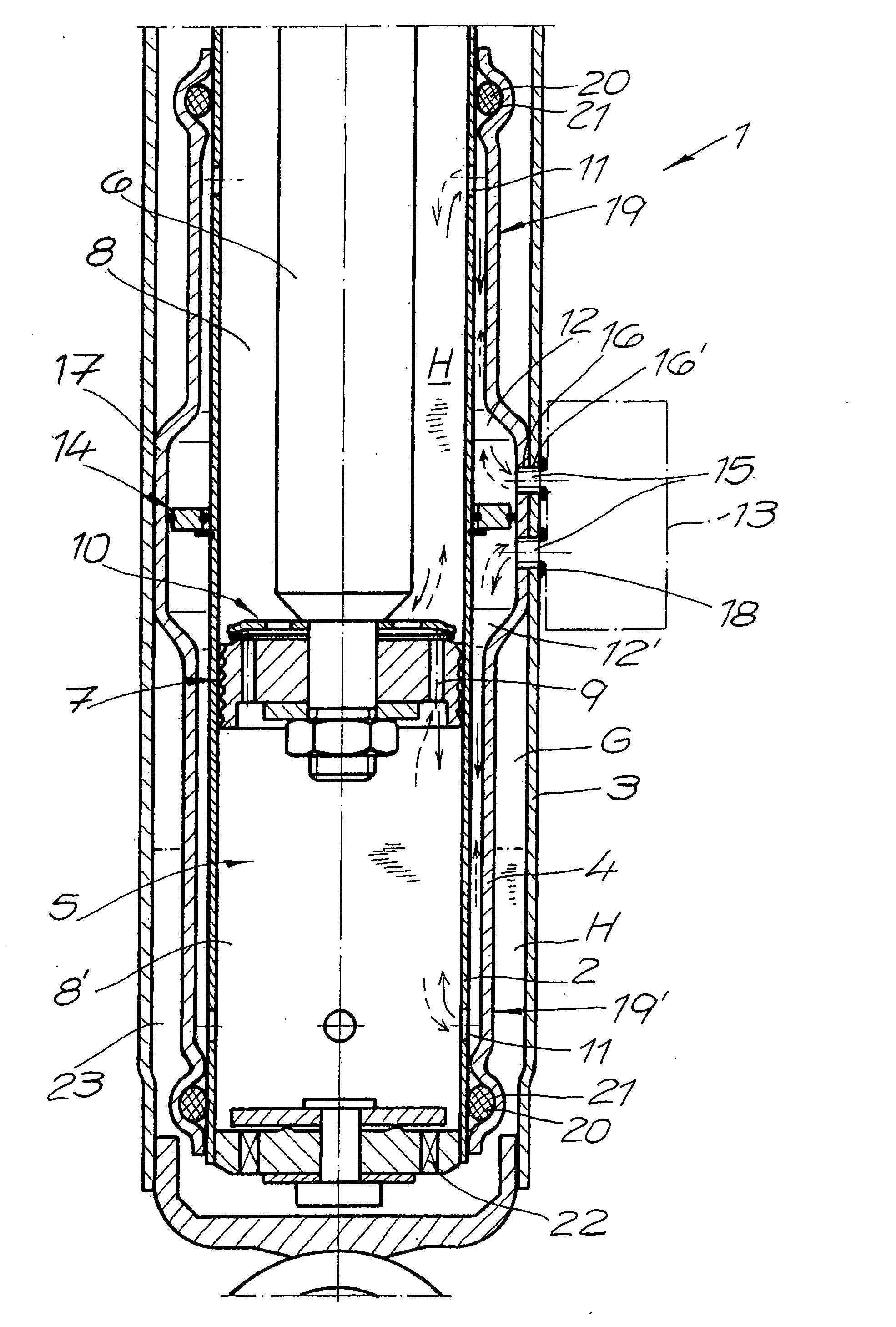
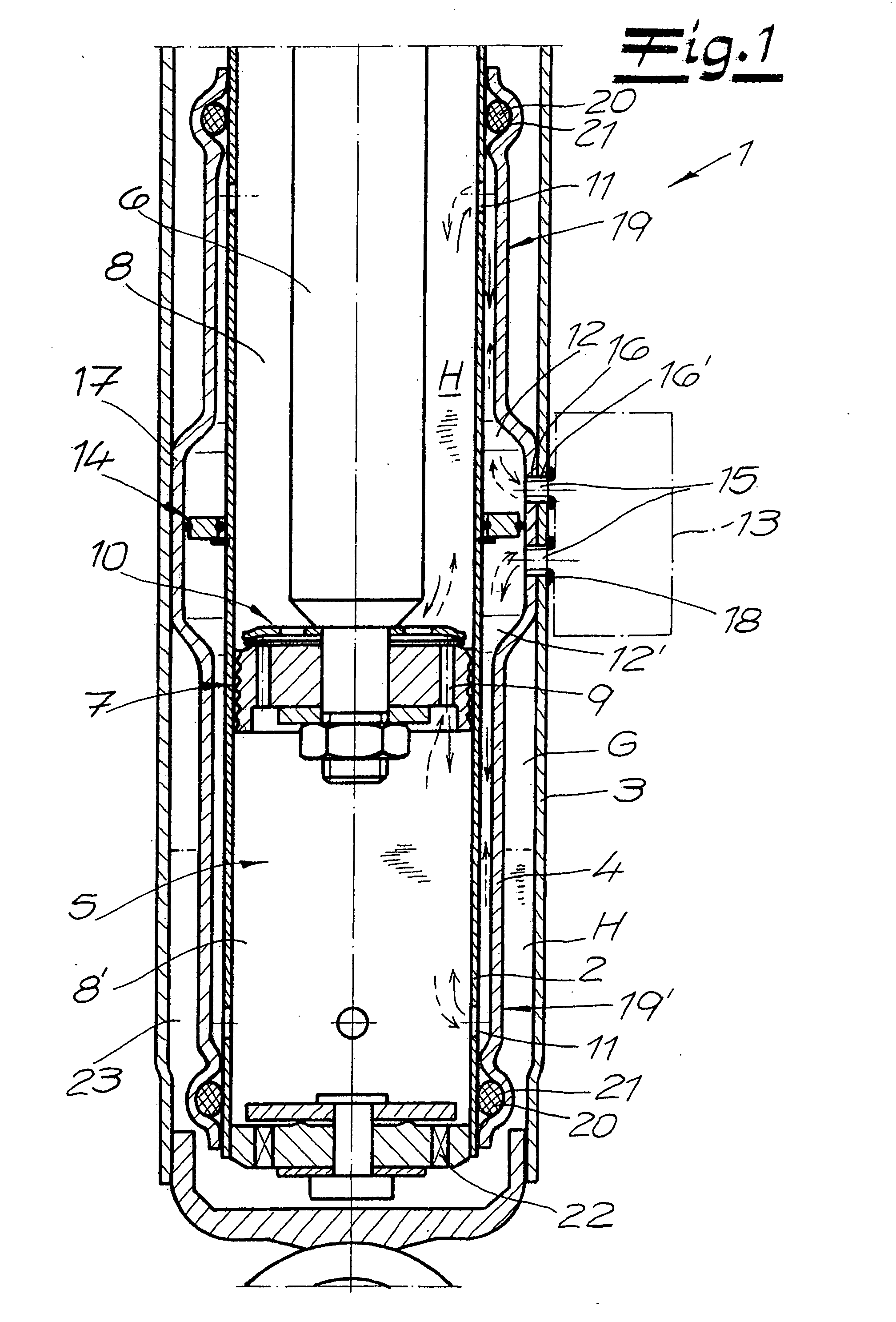
[0024]Referring now in detail to the drawings, FIG. 1 shows a vibration damper 1, particularly for motor vehicles. Vibration damper 1 has an inner pipe 2, an outer pipe 3 that surrounds inner pipe 2, and a center pipe 4 that is disposed between inner pipe 2 and outer pipe 3. Inner pipe 2 encloses a working space 5 that is filled with hydraulic fluid H. A piston 7 is disposed on a piston rod 6, guided in displaceable manner, which piston divides the working space 5 into a chamber 8 on the piston rod side and a chamber 8′ away from the piston rod.

[0025]The piston rod 6 is passed out, in usual manner, through a sealing and guidance element, not shown, at the upper end of inner pipe 2, to be connected to the chassis structure. In usual manner, passage channels 9 and valve elements 10 are disposed in the piston 7.

[0026]When movement of the piston rod 6 occurs, hydraulic fluid H can flow from one of chambers 8, 8′ into the other, through passage channels 9 and valve elements 10 of piston ...


PUM


Abstract

A hydraulic vibration damper has an inner pipe, a center pipe, and an outer pipe. A piston on a piston rod is guided to be displaceable in a working space that is formed by the inner pipe. Flow spaces that are hydraulically separated from one another and connected with a valve module are formed between inner pipe and center pipe. The center pipe has a radially projecting formed-out part, at which the center pipe is connected with the outer pipe or the inner pipe, via a press fit. The passage openings of the center pipe and of the outer pipe are disposed in the region of the formed-out part. Also, a separation system for hydraulic separation of the flow spaces is situated in the region of the formed-out part. Also provided is a method for the production of a three-pipe system for a vibration damper.

Description

CROSS REFERENCE TO RELATED APPLICATIONS[0001]Applicants claim priority under 35 U.S.C. 119 of German Application No. 10 2007 054 275.7 filed Nov. 14, 2007.BACKGROUND OF THE INVENTION[0002]1. Field of the Invention[0003]The present invention relates to a hydraulic vibration damper, particularly for motor vehicles, having an inner pipe, an outer pipe that surrounds the inner pipe, and a center pipe that is disposed between inner pipe and outer pipe. The inner pipe encloses a working space that is filled with hydraulic fluid, which space is divided into two chambers by a piston that is disposed on a piston rod and guided to be displaced in the working space. A flow space on the piston rod side and a flow space away from the piston rod are formed between the inner pipe and the center pipe, which spaces are hydraulically separated from one another and connected with a valve module disposed on the outer pipe, by way of a passage opening in the center pipe and a passage opening in the oute...

Claims


Application Information

Patent Timeline
Patent Type & Authority Applications(United States)
IPC IPC(8): F16F9/00
CPCF16F9/46F16F9/185
Inventor KOLZ, BERTHOLD
Owner THYSSENKRUPP BILSTEIN
Why Eureka
Try Eureka