Wire break detecting device for wire electric discharge machine

a technology of electric discharge machine and detection device, which is applied in the direction of electrical-based machining electrodes, welding apparatus, manufacturing tools, etc., can solve the problems of sudden breakage of wire electrodes, damage to the workpiece surface to be machined, etc., to suppress consumption of power feeding elements and damage to the workpiece surface. , the effect of rapid detection of a wire electrode breakag

Inactive Publication Date: 2009-05-14
FANUC LTD
View PDF4 Cites 7 Cited by
  • Summary
  • Abstract
  • Description
  • Claims
  • Application Information

AI Technical Summary

Benefits of technology

[0009]Therefore, it is an object of the present invention to provide a wire break detecting device for a wire electric discharge machine which can rapidly detect a break in a wire electrode without affecting electric discharge machining itself, and which can suppress consumption of power feeding elements and damage to a workpiece surface to be machined.

Problems solved by technology

If improper conditions are set, machining may become unstable and the wire electrode may be suddenly broken in some cases.
If DC voltage from a machining power source is applied to the wire electrode immediately after the break, consumption of power feeding elements and damage to a workpiece surface to be machined occur.
However, this technique can detect the break only by feeding discharge current or short-circuit current from the machining power source.
Therefore, when the current is fed, the power feeding elements may be consumed and damage to the workpiece surface to be machined may be caused.
With this technique, however, the test voltage is superimposed on the machining voltage to generate potential gradient in the wire electrode, which may adversely affect machining by causing variation in machining results, for example.

Method used


Image

  • Wire break detecting device for wire electric discharge machine
  • Wire break detecting device for wire electric discharge machine
  • Wire break detecting device for wire electric discharge machine

Examples


Embodiment Construction

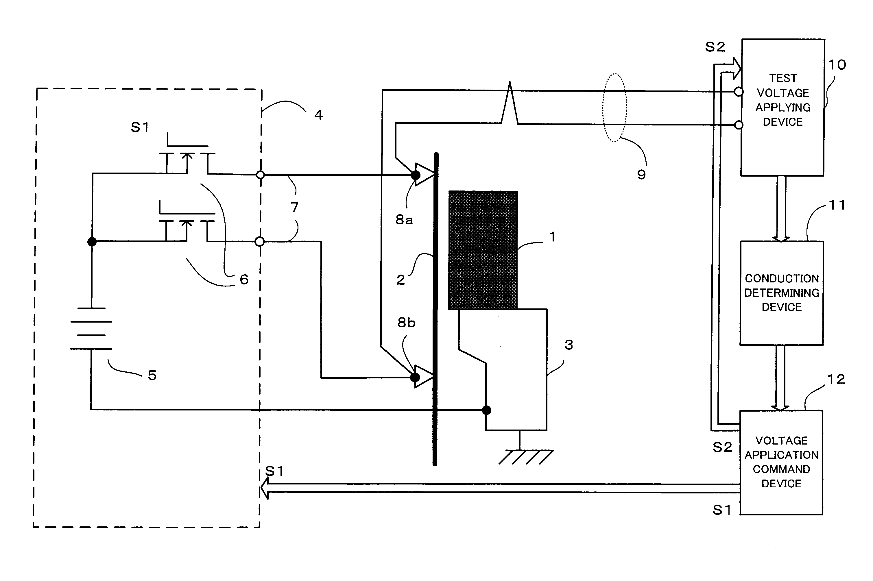
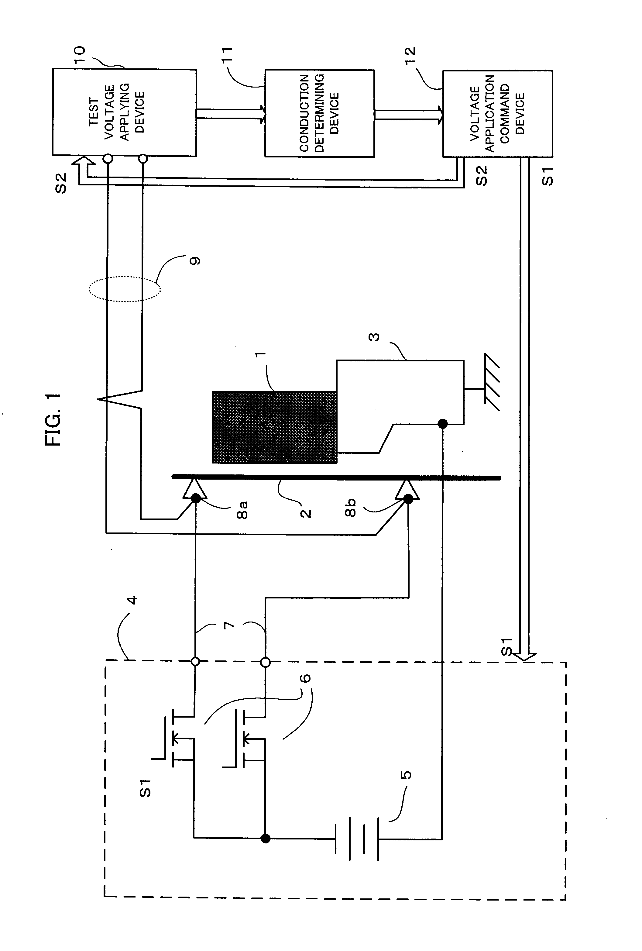
[0018]FIG. 1 is a schematic block diagram of an embodiment of a wire break detecting device according to the present invention.

[0019]A machining power source 4 includes a machining DC voltage source 5 and switching devices 6. The switching devices 6 converts DC voltage from the machining DC voltage source 5 to a pulse voltage and applies the pulse voltage to a wire electrode. One of electrodes of the machining DC voltage source 5 is connected to an upper power feeding elements 8a and to a lower power feeding element 8b via the switching devices 6 and power supply lines 7 and the other electrode is connected to a workpiece mounting table 3.

[0020]An application command signal S1 is input to the switching devices 6 from a voltage application command device 12. Based on the application command signal S1, the switching devices 6 convert the DC voltage from the machining DC voltage source 5 so that a cycle of a voltage applying time and a quiescent period is repeated at high frequency dur...


PUM

PropertyMeasurementUnit
reference voltageaaaaaaaaaa
voltageaaaaaaaaaa
DC voltageaaaaaaaaaa

Abstract

In electric discharge machining for intermittently applying voltage pulses between a wire electrode and a workpiece with quiescent periods interposed, test voltage for checking conduction between upper and lower power feeding elements is applied during quiescent periods. When there is no conduction, it is determined that the wire electrode is broken between the upper and lower power feeding elements.

Description

BACKGROUND OF THE INVENTION[0001]1. Field of the Invention[0002]The present invention relates to a wire break detecting device for a wire electric discharge machine for detecting a break in a wire electrode of a wire electric discharge machine.[0003]2. Description of the Related Art[0004]The wire electric discharge machine generates intermittent discharge between a wire electrode and a workpiece (between electrodes) and relatively moves the wire electrode with respect to the workpiece according to a state between the electrodes, to thereby remove and machine the workpiece. To generate the intermittent discharge, a series of operations including application of direct current between the electrodes and then insertion of quiescent period are repeated.[0005]Before machining, machining conditions are set. If improper conditions are set, machining may become unstable and the wire electrode may be suddenly broken in some cases. If DC voltage from a machining power source is applied to the ...

Claims


Application Information

Patent Timeline
Patent Type & Authority Applications(United States)
IPC IPC(8): B23H1/00
CPCB23H7/02B23H7/102B23H7/04
Inventor KAWAHARA, AKIYOSHINAKASHIMA, YASUO
Owner FANUC LTD
Why Eureka
Try Eureka