
Implementation of wavelength shifters in phoswich detectors

a detector and wavelength shifter technology, applied in the field of nuclear medical imaging, can solve the problems of reducing the spatial resolution of the scintillator, difficult to make a scintillator with good pet properties, and not being well matched for use with other silicon-based photodetectors

Active Publication Date: 2009-05-14
UNIV OF TENNESSEE RES FOUND
View PDF7 Cites 25 Cited by
  • Summary
  • Abstract
  • Description
  • Claims
  • Application Information

AI Technical Summary

Benefits of technology

[0010]The present invention solves the existing need in the art to determine the depth of interaction for a PET detector using different scintillation materials in a phoswich detector. The present invention uses a wavelength shifting layer (WLS) as an interface between LSO and, for example, LuAP in a phoswich combination. A unique scintillator identification can be assisted by using a wavelength shifting material to absorb light at a short wavelength (higher energy) and re-emit the light at a longer...

Problems solved by technology

LSO is a very good scintillator for a PMT but it is not well matched for use with other silicon-based photodetectors such as avalanche photodiodes (APDs) and silicon photomultipliers (SiPMs).
It is difficult to make a scintillator with good PET properties and to make it emit at an exact wavelength for photodetection.
In the absence of DOI information, however, the thickness of the scintillator reduces the spatial resolution due to parallax error.
However, the functionality of these phoswich combinations is somewhat limited because both LuAP and LaBr3 emit in the excitation band of LSO, YSO or LYSO.
However, since the emission of LuAP and LaBr3 scintillators are in the excitation band of LSO, both scintillators will be activated by a single 511 keV absorption and it is thus difficult to achieve a unique scintillation layer identification.

Method used


Image

  • Implementation of wavelength shifters in phoswich detectors
  • Implementation of wavelength shifters in phoswich detectors
  • Implementation of wavelength shifters in phoswich detectors

Examples


first embodiment

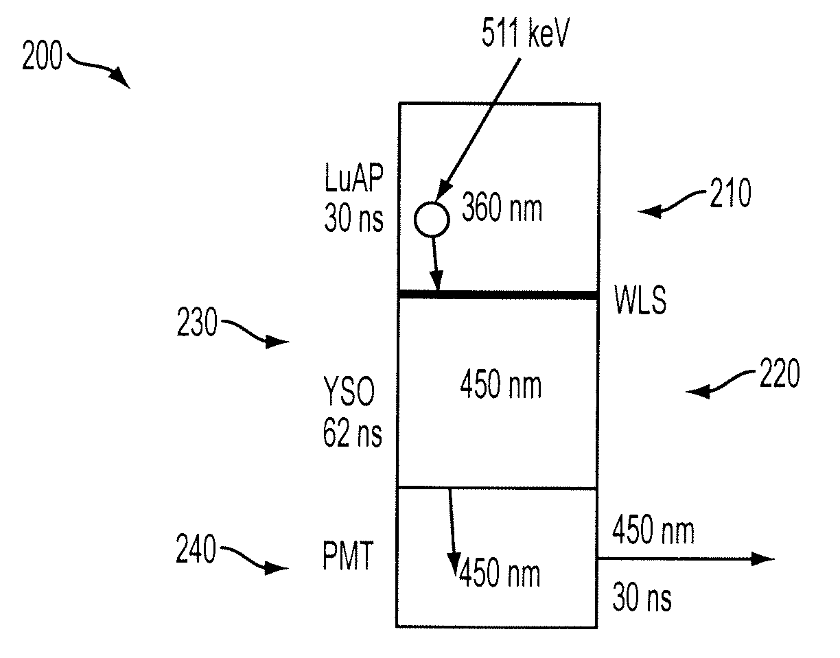
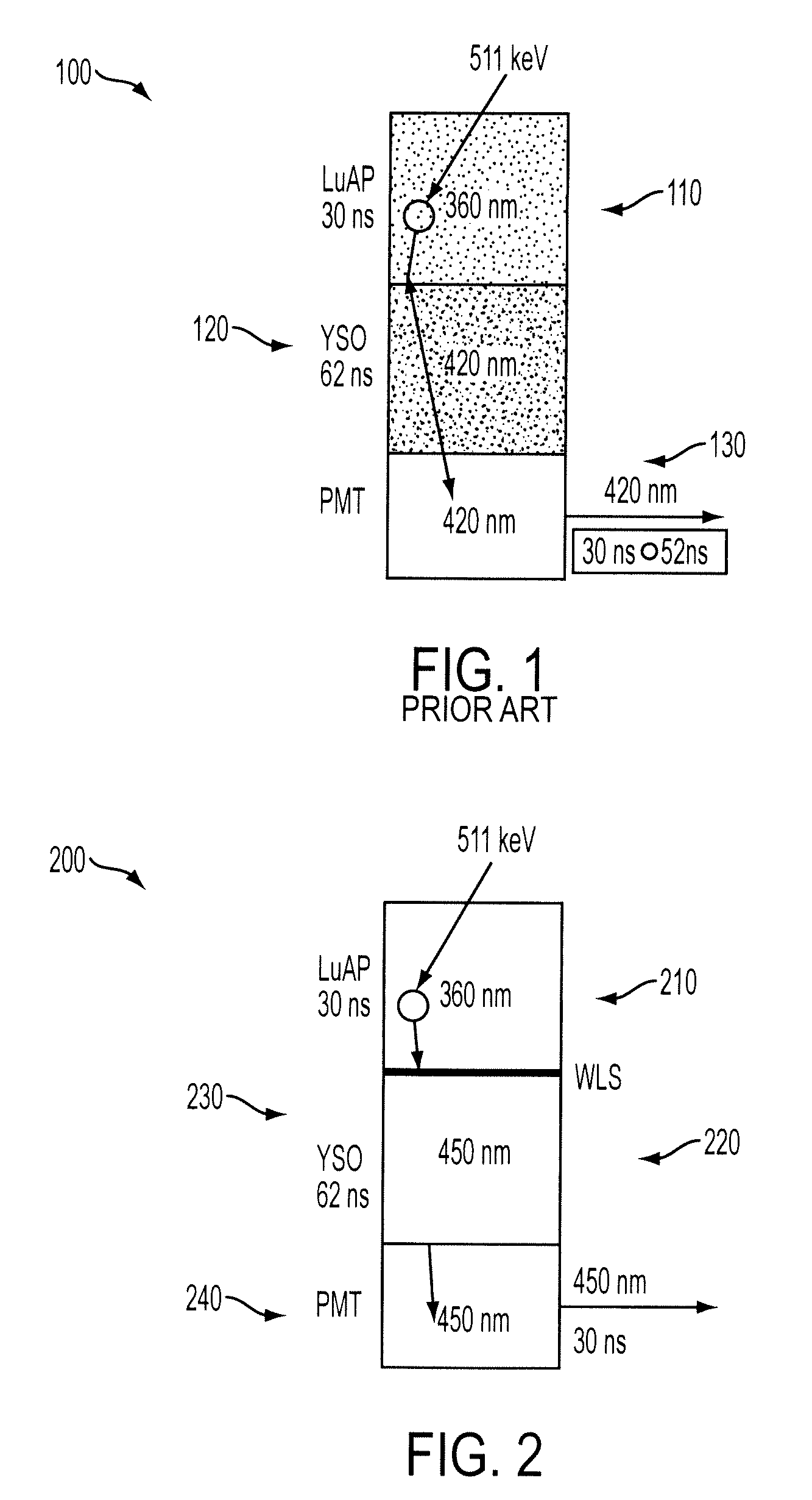
[0026]FIG. 2 depicts the present invention, comprising a phoswich device 200. The phoswich device 200 includes a LuAP scintillator 210, a YSO scintillator 230, and a fast wavelength shifting layer 220 between the LuAP and YSO scintillators. When a 511 keV gamma photon is absorbed in the LuAP scintillator 210, it emits light scintillations around 360 nm. The light photons travel out of the LuAP scintillator 210 and are absorbed by fast wavelength shifting layer 220, which has a scintillation time of approximately 3 ns. The wavelength shifting layer 220 converts the LuAP light emission from 360 nm to 450 nm while still keeping most of the LuAP decay time characteristics. The converted 450 nm light travels through the YSO scintillator 230 without exciting any response from the YSO crystal as the 450 nm is outside of the YSO excitation band. The 450 nm light exits from the YSO crystal 230 and enters into the PMT 240. The PMT 240 thus sees 450 nm light with a decay time characteristic su...

third embodiment

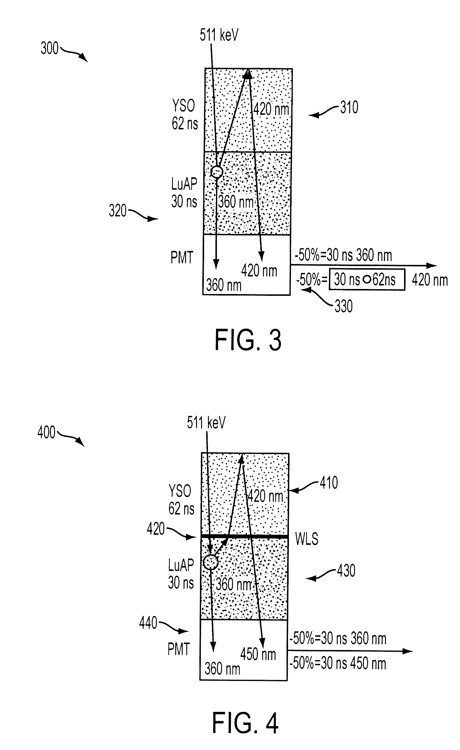
[0031]Finally, FIGS. 7 and 8 relate to the invention, which is directed to a phoswich combination of LaBr3 and LSO, similar to the embodiment of FIG. 2. FIG. 7 shows a phoswich 700 with an LaBr3:Ce (0.5% Ce, 25 ns scintillation decay time) scintillator 710 directly coupled to an LSO:Ce scintillator 720. When a 511 keV gamma interacts with the LaBr3 scintillator, 360 nm light is produced, which is absorbed by and excites the LSO scintillator, producing 420 nm light which is seen by the PMT. On the other hand, when a 511 keV gamma photon is stopped by the LSO scintillator, it causes 420 nm light to be directly produced by the LSO scintillator. The scintillation time characteristics seen by the PMT 730 in this case thus are the convolved LaBr3-LSO pulse and the direct LSO:Ce pulse.

[0032]In FIG. 8 a phoswich 800 has a thin wavelength shifter 820 (WLS, e.g., Eljen EJ299-21) between an LaBr3:Ce (0.5% Ce, 25 ns scintillation decay time) scintillator 810 and an LSO:Ce scintillator 830. The ...


PUM


Abstract

A phoswich device for determining depth of interaction (DOI) includes a wavelength shifting layer between first and second scintillators of different scintillation materials and having different decay time characteristics. The wavelength shifting layer allows a true phoswich device to be constructed where the emission wavelength of one scintillator is in the peak excitation band of the other scintillator, by shifting the scintillation light outside of this excitation band to prevent scintillation light of one scintillator from exciting a response in the other scintillator, thus enabling unique identification of the location of a gamma photon scintillation event. The phoswich device is particularly applicable to positron emission tomography (PET) applications.

Description

CROSS-REFERENCE TO RELATED APPLICATION AND CLAIM OF PRIORITY[0001]This application is a non-provisional of and claims priority to under 35 U.S.C. § 119(e) copending Application Ser. No. 60 / 914,411 filed Apr. 27, 2007.TECHNICAL FIELD[0002]The present invention is in the field of nuclear medical imaging. In particular, the present invention relates to techniques for accurate detection of emission radiation in nuclear medical imaging processes such as positron emission tomography (PET).BACKGROUND OF THE INVENTION[0003]Medical imaging is one of the most useful diagnostic tools available in modern medicine. Medical imaging allows medical personnel to non-intrusively look into a living body in order to detect and assess many types of injuries, diseases, conditions, etc. Medical imaging allows doctors and technicians to more easily and correctly make a diagnosis, decide on a treatment, prescribe medication, perform surgery or other treatments, etc.[0004]There are medical imaging processes ...

Claims


Application Information

Patent Timeline
IPC IPC(8): G01T1/166G01T1/164
CPCG01T1/20G01T1/2985G01T1/202G01T1/2008
Inventor ERIKSSON, LARS A.MELCHER, CHARLES L.GRAZIOSO, RONALD
Owner UNIV OF TENNESSEE RES FOUND
Learn More