
Method of manufacturing crystal oriented ceramics

a technology crystal oriented ceramics, which is applied in the field of crystal oriented ceramics manufacturing, can solve the problems of unleaded piezoelectric ceramics not being able to exhibit adequate piezoelectric characteristics, the piezoelectric characteristic of unleaded piezoelectric ceramics is lower, and the environmental burden is increased, so as to reduce the characteristic, improve the piezoelectric characteristic, and increase the curie temperatur

Inactive Publication Date: 2009-05-14
DENSO CORP
View PDF16 Cites 17 Cited by
  • Summary
  • Abstract
  • Description
  • Claims
  • Application Information

AI Technical Summary

Benefits of technology

[0055]Reference to “x” represents an amount of Li that is substituted with K and / or Na representing the A-site element. Substituting the parts of K and / or Na by Li, the crystal oriented ceramics can obtain various advantageous effects such as an increase in piezoelectric characteristic, an increase in Curie temperature and / or an acceleration in densification.
[0056]A range of “x” in the general formula (2) may preferably satisfy the relationship expressed as 0<x≦0.2.
[0057]In this case, the compound, expressed by the general formula (2) described above, has Li as an essential component. This allows the crystal oriented ceramics to be sintered in a further easy manner during production thereof, with accompanying improvement in piezoelectric characteristic and a further increase in Curie temperature (Tc). This is because selecting Li as the essential component within the range of “x” results in a capability of causing a drop in sintering temperature while permitting Li to play a role as a sintering aids to make it possible to achieve the sintering with the occurrence of fewer voids.
[0058]If a value of “x” exceeds 0.2, a risk arises with the occurrence of a drop in piezoelectric characteristic (piezoelectric d33 constant, electromechanical coupling coefficient kp, piezoelectric 931 constant or the like).
[0059]Further; the value of “x” in the general formula (2) may preferably satisfy the relationship x=0.
[0060]In this case, the general formula (2) can be rewritten as (K1−yNay)(Nb1−z−wTazSbw)O3, In such a case, when manufacturing the crystal oriented ceramics, the raw material for such ceramics does not contain a compound like, for instance, LiCO3 that contains the lowest lightweight component of Li. This enables a reduction in characteristic due to segregation of a raw material powder when mixing the raw material to manufacture the crystal oriented ceramics. In such a case, further, it becomes possible to realize a high relative permittivity and a relatively large piezoelectric g constant. In the general formula (2), “x” may lay in the relationship expressed as 0≦x≦0.15 and, more preferably, 0≦x≦0.10.

Problems solved by technology

However, the piezoelectric ceramics of such a lead family contains lead oxide with high vapor pressure, with an accompanying issue with an increase of environmental burdens.
However, these unleaded piezoelectric ceramics have problems with piezoelectric characteristics being lower than that of PZT.
However, an issue arises in that these unleaded piezoelectric ceramics cannot exhibit adequately higher piezoelectric characteristic than those of the piezoelectric ceramics of the PZT family.
However, with the manufacturing method of such a related art, even if an attempt is made to manufacture the crystal oriented ceramics with the plate-like powders being oriented, an issue is sometimes encountered with the occurrence of variation in orientation degrees of the crystal grains subsequent to the sintering step.
This results in a difficulty of obtaining the crystal oriented ceramics with an increased orientation degree.
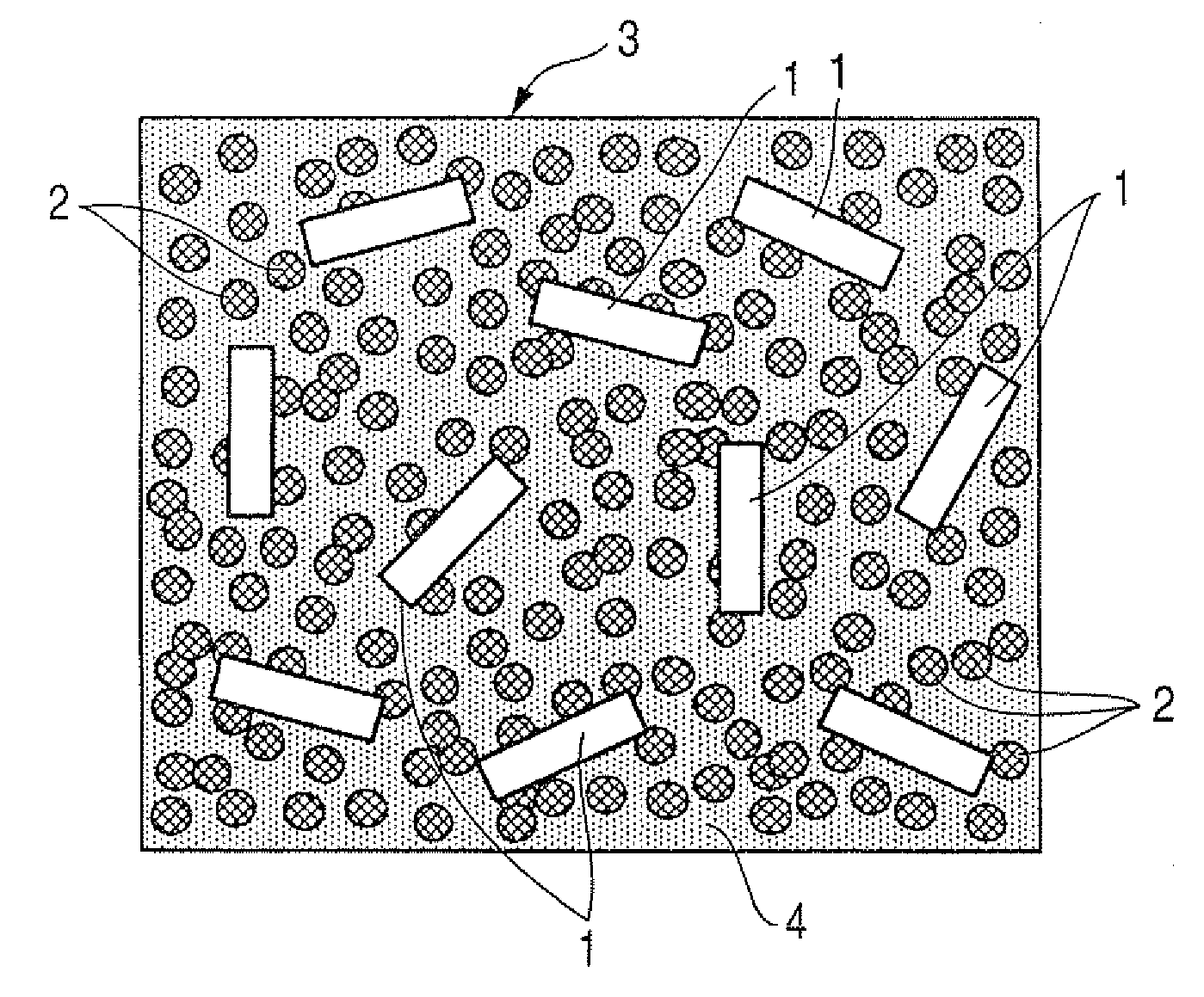
Further, during a step of manufacturing a polycrystalline body (crystal oriented ceramics) composed of ceramics upon sintering the plate-like powders and the raw material powders, the plate-like powders and the raw material powders, different from each other in grain diameter, tend to be sintered with an accompanying issue arising with a difficulty of obtaining a dense polycrystalline body.

Method used


Image

  • Method of manufacturing crystal oriented ceramics
  • Method of manufacturing crystal oriented ceramics
  • Method of manufacturing crystal oriented ceramics

Examples


example 1

[0193]Next, an example 1 of the first aspect of the present invention will be described below.

[0194]With the present example 1, a crystal oriented ceramics was manufactured in a composition formed in a polycrystalline body, containing an isotropic perovskite-based compound formed in a principal phase, which was constituted with crystal grains with a specific crystal plane ({100} plane) being oriented.

[0195]In the present example 1, the crystal oriented ceramics was manufactured in the composition in which 0.0005 mol of Mn was externally added to 1 mol of {Li0.065(K0.45Na0.55)0.935}{Nb0.83Ta0.09Sb0.08)O3.

[0196]In manufacturing the crystal oriented ceramics of the present example 2, the preparing step, the mixing step, the shaping step and the sintering step were conducted.

[0197]In the preparing step, the anisotropically shaped powder and the microscopic powder were prepared. The anisotropically shaped powder was composed of the anisotropically shaped oriented grains composed of the i...

example 2

[0309]Next, an example 2 of the second aspect of the present invention will be described below.

[0310]With the present example 2, a crystal oriented ceramics was manufactured in a composition of a polycrystalline body, containing an isotropic perovskite-based compound formed in a principal phase, which has crystal grains with a specific crystal plane ({100} plane) being oriented.

[0311]In the present example 2, the crystal oriented ceramics was manufactured in the composition in which 0.0005 mol of Mn is externally added to 1 mol of {Li0.065(K0.45Na0.55)0.935}{Nb0.83Ta0.09Sb0.08)O3.

[0312]In manufacturing the crystal oriented ceramics of the present example 2, the preparing step, the mixing step, the shaping step and the sintering step were conducted.

[0313]In the preparing step, the anisotropically shaped powder and the microscopic powder were prepared. The anisotropically shaped powder was composed of the anisotropically shaped oriented grains composed of the isotropic perovskite-base...


PUM


Abstract

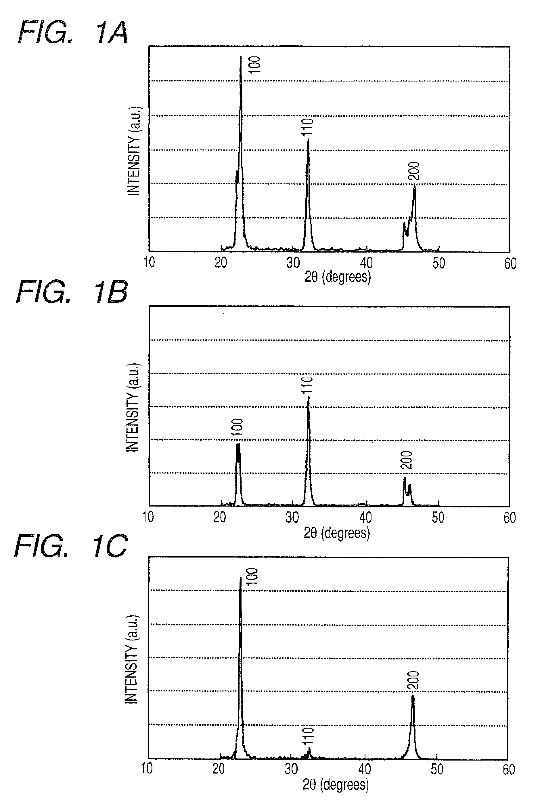
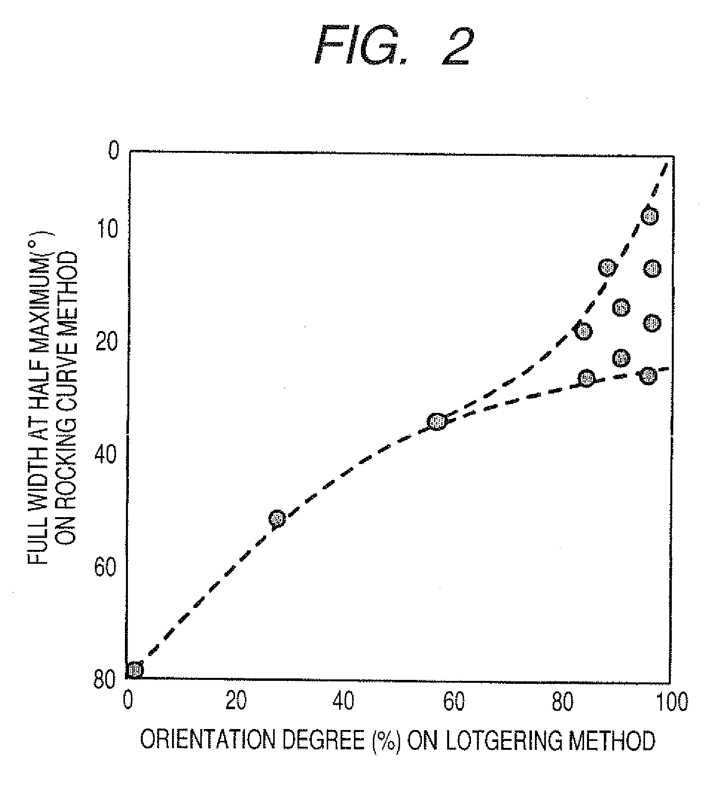
A method of manufacturing a crystal oriented ceramics is disclosed. The method comprises preparing step, mixing step, shaping step and sintering method. At least one of anisotropically shaped powder, used as raw material, and a compact, formed by shaping step, is selected to have an orientation degree of 80% or more with a full width at half maximum (FWHM) of 15° or less according to a rocking curve method. A microscopic powder, having an average grain diameter one-third or less that of anisotropically shaped powder, is prepared for mixing therewith to prepare raw material mixture. The raw material mixture is shaped into the compact so as to allow oriented planes of anisotropically shaped powder to be oriented in a nearly identical direction. In a sintering step, anisotropically shaped powder and microscopic powder are sintered with each other to obtain the crystal oriented ceramics.

Description

CROSS REFERENCE TO RELATED APPLICATIONS[0001]This application is related to Japanese Patent Application Nos. 2007-290974 and 2007-290975, both filed on Nov. 8, 2007, the contents of which are hereby incorporated by reference.BACKGROUND OF THE INVENTION[0002]1. Technical Field of the Invention[0003]The present invention relates to methods of manufacturing crystal oriented ceramics and, more particularly, to a method of manufacturing a crystal oriented ceramics formed in a polycrystalline body having a principal phase formed of an isotropic perovskite-based compound composed of crystal grains each of which has an oriented specific crystal plane.[0004]2. Description of the Related Art[0005]A polycrystalline body, composed of ceramics, has been widely used in various sensors such as sensors for detecting, for instance, a temperature, heat, gas and ions or the like. Further, the polycrystalline body has been utilized in electronic fields of electronic component parts such as a capacitor,...

Claims


Application Information

Patent Timeline
Patent Type & Authority Applications(United States)
IPC IPC(8): C04B35/46B29C67/00
CPCC04B35/495C04B2235/787C04B2235/3201C04B2235/3203C04B2235/3255C04B2235/3267C04B2235/3294C04B2235/3298C04B2235/5292C04B2235/5296C04B2235/5436C04B2235/5445C04B2235/6562C04B2235/6565C04B2235/768C04B2235/77C04B35/6262
Inventor SHIBATA, DAISUKENAKAMURA, MASAYAKIMURA, HIDEKINAGAYA, TOSHIATSUYAMAGUCHI, HIROTAKA
Owner DENSO CORP
Learn More