Imaging device and lens array used therein
a technology of imaging device and lens array, which is applied in the field of compound eye type imaging device, can solve the problems of large lens diameter, volume increase, and insufficiently achieved size reduction, and achieve the effect of high image resolution
- Summary
- Abstract
- Description
- Claims
- Application Information
AI Technical Summary
Benefits of technology
Problems solved by technology
Method used
Image
Examples
embodiment 1
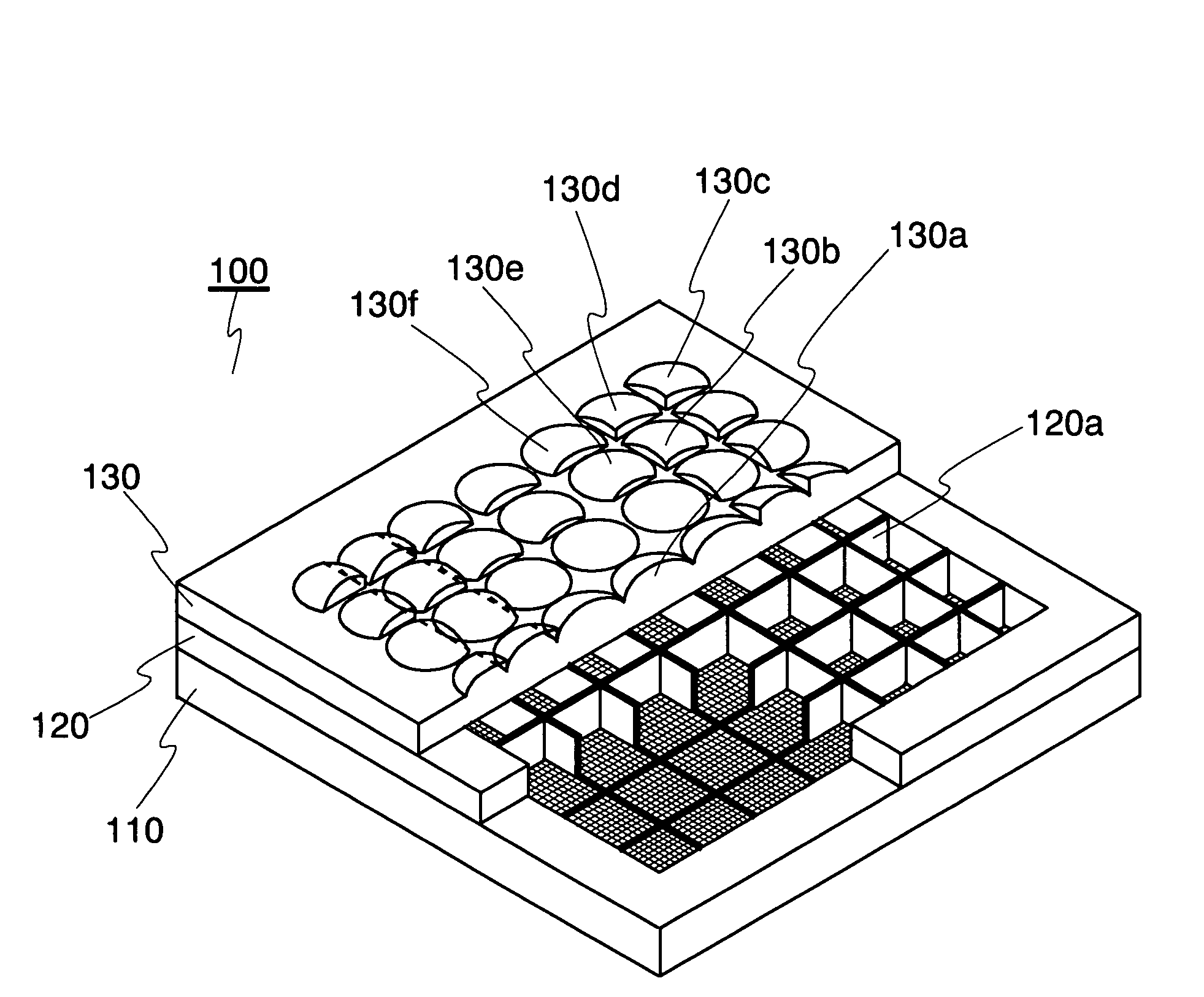
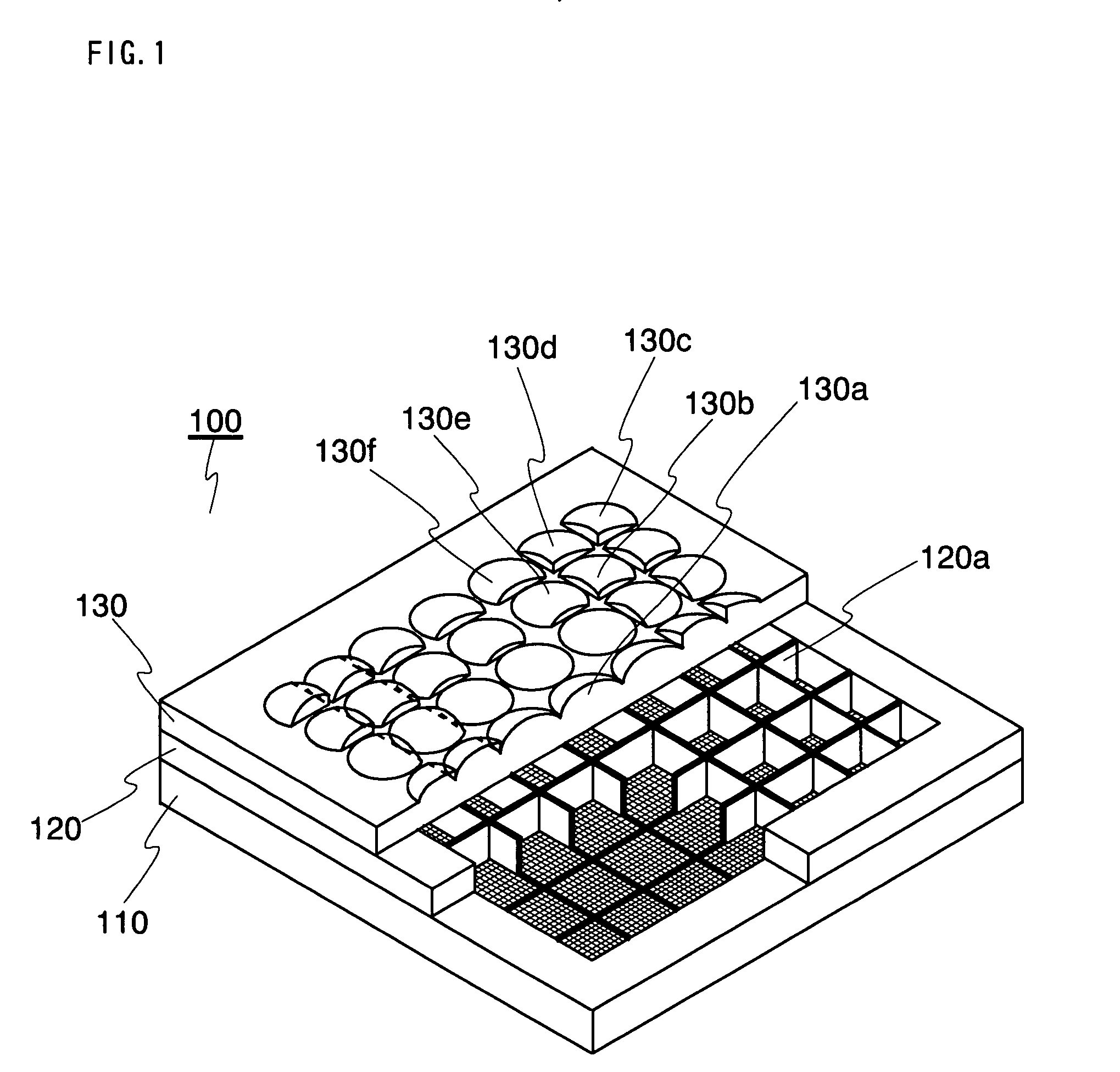
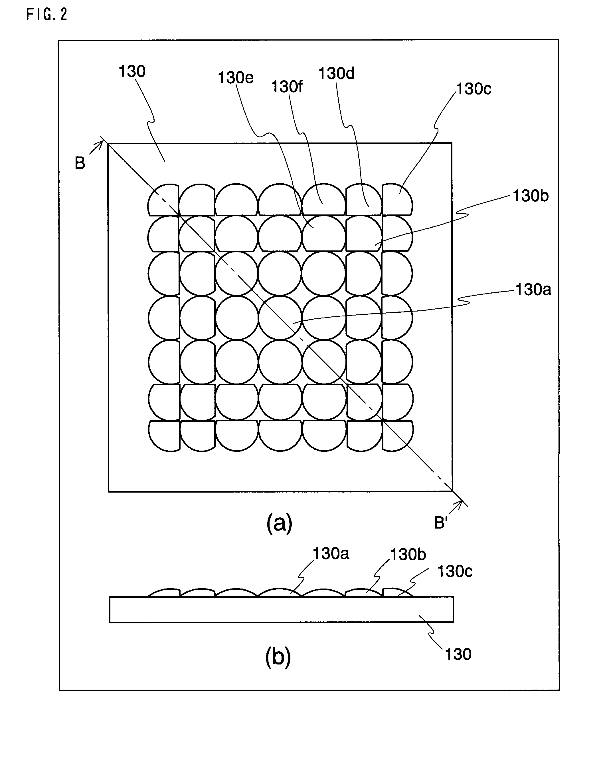
[0042]FIG. 1 is a part-removed perspective view showing a configuration of an imaging device according to Embodiment 1. Further, FIG. 2 is a schematic diagram showing a lens array of the imaging device according to Embodiment 1. FIG. 2(a) is a plan view of the lens array, while FIG. 2(b) is a side view of the lens array. In FIG. 1, the imaging device 100 includes an image sensor 110, a partition member 120 and a lens array 130.
[0043]The image sensor 110 has a light acceptance surface composed of a large number of photoelectric conversion sections each corresponding to a pixel. The image sensor 110 converts incident light that is incident on the light acceptance surface, into an electric signal in accordance with the intensity, and then outputs the signal as an electric image signal to the outside. The light acceptance surface of the image sensor 110 includes rectangular imaging regions 110a to 110f (numerals are not indicated in FIG. 1) and the like each composed of a plurality of p...
embodiment 2
[0061]FIG. 4 is a part-removed perspective view showing a configuration of an imaging device according to Embodiment 2. Further, FIG. 5 is a schematic diagram showing a lens array of an imaging device according to Embodiment 2. FIG. 5(a) is a plan view of the lens array, while FIG. 5(b) is a side view of the lens array. The imaging device 200 according to Embodiment 2 has the same basic configuration as the imaging device 100 according to Embodiment 1. Thus, hereinafter, parts having a new feature depending on a difference point are solely described. In FIG. 4, the imaging device 200 includes an image sensor 210, a partition member 220 and a lens array 230.
[0062]A feature of the imaging device 200 is that all imaging units have a lens element provided with an optical axis in agreement with the axis passing through the center of the corresponding imaging region and have an axial symmetric lens face having the shape of a circle approximately inscribing the imaging region. That is, in ...
embodiment 3
[0070]FIG. 7 is a part-removed perspective view showing a configuration of an imaging device according to Embodiment 3. Further, FIG. 8 is a schematic diagram showing a lens array of an imaging device according to Embodiment 3. FIG. 8(a) is a plan view of the lens array, while FIG. 8(b) is a side view of the lens array. The imaging device 300 according to Embodiment 3 has the same basic configuration as the imaging device 100 according to Embodiment 1. Thus, hereinafter, parts having a new feature depending on a difference part are solely described.
[0071]In the imaging device 300, the image sensor 110 and the partition member 120 have the same structures as those of the imaging device 100. Thus, the imaging device 300 is constructed such that the areas of the imaging regions of imaging units located in the periphery part distant from the center part of the image sensor should be smaller than the areas of the imaging regions of imaging units located in the center part of the image se...
PUM
 Abstract
Description
Claims
Application Information
 - R&D
- Intellectual Property
- Life Sciences
- Materials
- Tech Scout
- Unparalleled Data Quality
- Higher Quality Content
- 60% Fewer Hallucinations
Browse by: Latest US Patents, China's latest patents, Technical Efficacy Thesaurus, Application Domain, Technology Topic, Popular Technical Reports.
© 2025 PatSnap. All rights reserved.Legal|Privacy policy|Modern Slavery Act Transparency Statement|Sitemap|About US| Contact US: help@patsnap.com


