Dispersion compensating apparatus

a compensating apparatus and dispersion technology, applied in the direction of instruments, optical elements, optics, etc., can solve the problems of wavelength dispersion, increase the transmission speed of optical signals, and increase the degradation of optical signal pulse waveforms

Inactive Publication Date: 2009-05-14
FUJITSU LTD
View PDF7 Cites 14 Cited by
  • Summary
  • Abstract
  • Description
  • Claims
  • Application Information

AI Technical Summary

Benefits of technology

[0031]It is an object of the present invention to at le...

Problems solved by technology

Therefore, degradation of the pulse waveform of the optical signal increases as the transmission distance of the optical signal increases.
Wavelength dispersion is a significant obstacle that restricts transmission distance especially in recent optical communication systems that significantly increase the transmission speed of optical signals.
However, a problem exists with the conventional techniques in that, when the thickness of the resonating cavity in the etalon is reduced to expand the band, the magnitude of dispersion compensation decreases and, therefore, sufficient dispersion compensation can not be realized.
On the other hand, when the reflectance of each partially reflective film of the etalon is increased to increase the magnitude of dispersion compensation, a problem arises in that the effective band becomes narrow and, therefore, high-speed optical transmission is not possible.
Further, when the reflectance of each partially reflective film of an etalon is increased, loss of the optical signal increases caused by the reflection efficiency of the reflective films and the absorption of light by the material of the cavity.
Therefore, the dispersion compensating apparatus can not be applied to an optical signal of a 40 Gb/s system.
That is, the variable r...

Method used


Image

  • Dispersion compensating apparatus
  • Dispersion compensating apparatus
  • Dispersion compensating apparatus

Examples


first embodiment

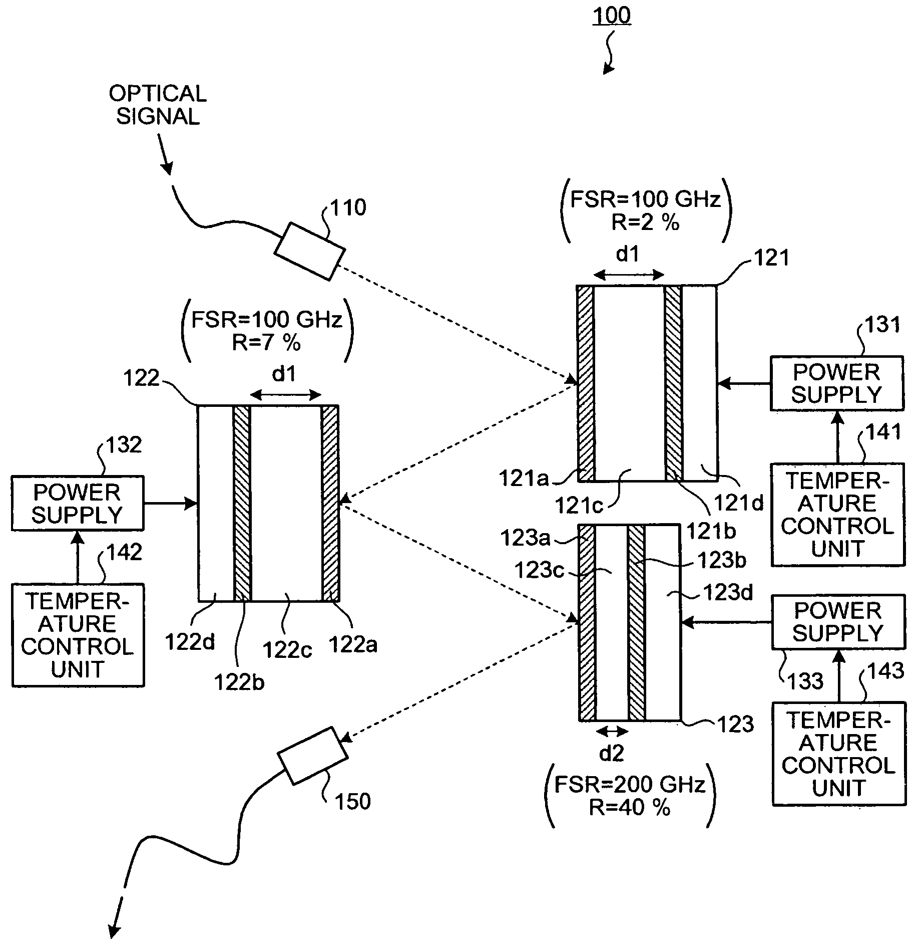
[0054]As shown in FIG. 1, a dispersion compensating apparatus 100 includes a collimator 110, etalons 121 to 123, power supplies 131 to 133, temperature control units 141 to 143, and a collimator 150. The collimator 110 collimates an optical signal input from an external source and transmits the optical signal to the etalon 121. The etalons 121 to 123 are reflection-type etalons that each impart a group delay for the optical signal that each etalon reflects, respectively.

[0055]The etalon 121 includes a partially reflective film 121a, a totally reflective film 121b, a resonating cavity 121c, and a Peltier element 121d. The partially reflective film 121a partially reflects at a predetermined reflectance R the optical signal transmitted from the collimator 110. An optical signal component not reflected by the partially reflective film 121a passes through the partially reflective film 121a. The totally reflective film 121b totally reflects the optical signal component that passes throug...

second embodiment

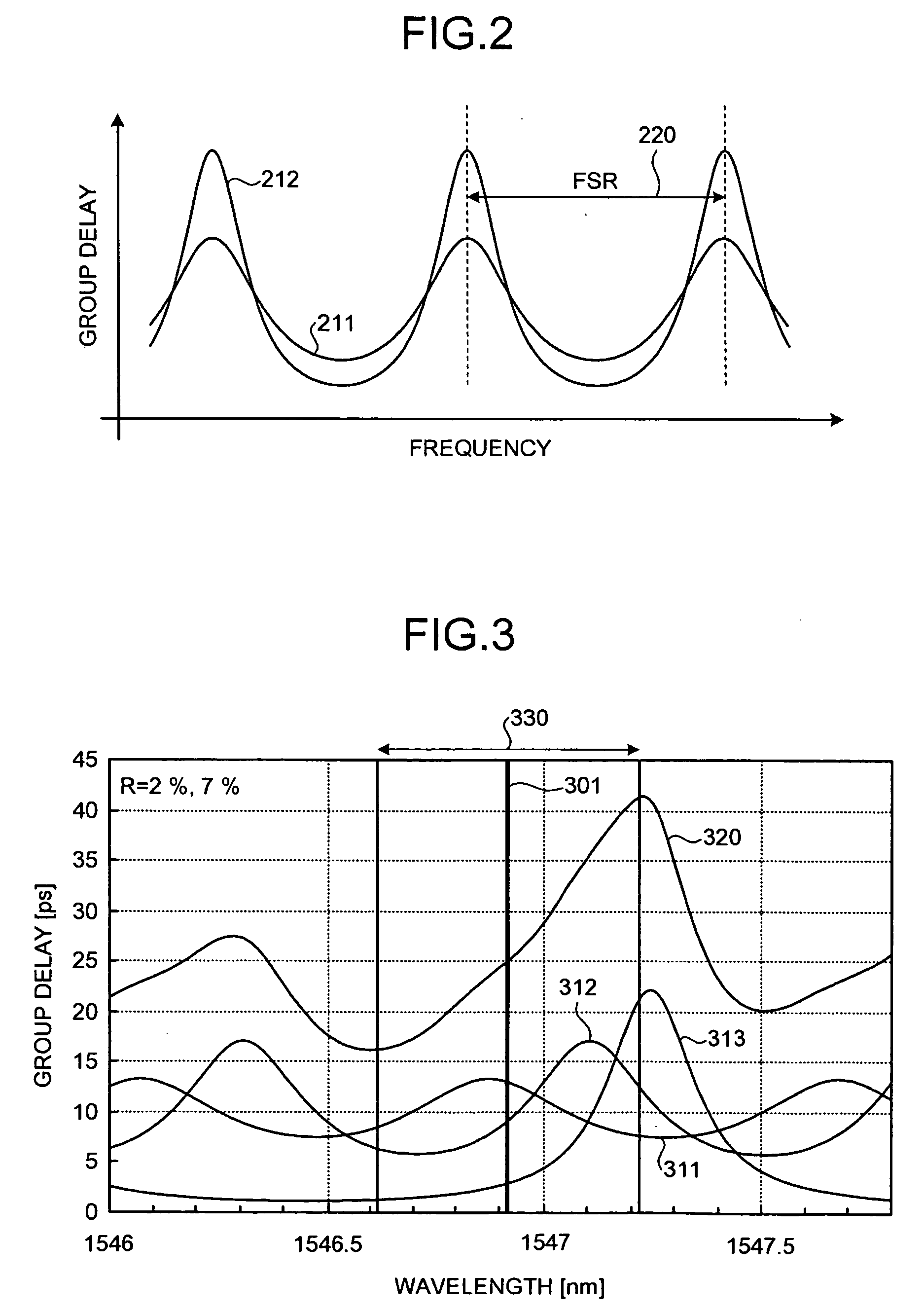
[0104]FIG. 8 is a graph indicating the group delay characteristics for each etalon according to the As shown in FIG. 8, components identical to those shown in FIG. 3 are given identical reference numerals and description thereof is omitted. As depicted in FIG. 8, the band 330 is approximately ±0.15 nm (approximately 1,546.8 to 1,547.1 nm). Therefore, the band 330 of the dispersion compensating apparatus 100 is approximately 35 GHz.

[0105]The combined group delay curve 320 represents the combined group delay characteristic having the maximum slope (magnitude of dispersion compensation) in the positive direction when the group delay curves 311 to 313 are appropriately shifted in terms of wavelength respectively using the temperature control units 141 to 143. The magnitude of dispersion compensation for the combined group delay curve 320 is 120 ps / nm.

[0106]The magnitude of dispersion compensation for the combined group delay curve 320 can be varied to −120 ps / nm by shifting in terms of...

third embodiment

[0114]As described above, the dispersion compensating apparatus 900 realizes the effect of the dispersion compensating apparatus 100 and, by combining the etalons 121 to 123 each respectively incorporated in a module, the combination of the etalons respectively having different FSRs and finesses can be easily changed. Therefore, the band and the magnitude of dispersion compensation can be easily adjusted corresponding to the characteristics of the optical signal.

[0115]In the module 910, by reflecting the optical signal plural times between the totally reflective mirror 912 and the etalon 121, the dispersion compensation can be adapted to be multi-staged in the one module. The same is true for the modules 920 and 930. Therefore, the magnitude of dispersion compensation can be increased while facilitating downsizing of the apparatus by reducing the number of etalons.

[0116]Description has been given for a case where the optical signal is reflected plural times by providing a totally r...


PUM


Abstract

A dispersion compensating apparatus compensates dispersion of an optical signal using reflection-type etalons. Each of the etalons reflects the optical signal and at least one etalon has, with respect to a group delay characteristic, a wavelength cycle and a finesse that are larger than those of the other etalons. Power supplies and temperature control units respectively shift, in terms of the wavelength, the group delay characteristics of the etalons.

Description

CROSS-REFERENCE TO RELATED APPLICATIONS[0001]This application is based upon and claims the benefit of priority from the prior Japanese Patent Application No. 2007-294175, filed on Nov. 13, 2007, the entire contents of which are incorporated herein by reference.BACKGROUND OF THE INVENTION[0002]1. Field of the Invention[0003]The present invention relates to a dispersion compensating apparatus that compensates dispersion of an optical signal using etalons.[0004]2. Description of the Related Art[0005]In the transmission of an optical signal using an optical fiber, the propagating velocity of the light differs for each wavelength component. Therefore, degradation of the pulse waveform of the optical signal increases as the transmission distance of the optical signal increases. This phenomenon is referred to as “wavelength dispersion”. Wavelength dispersion is a significant obstacle that restricts transmission distance especially in recent optical communication systems that significantly ...

Claims


Application Information

Patent Timeline
IPC IPC(8): H04B10/04G02B5/28G02B26/00H04B10/2507H04B10/2525H04B10/524
CPCG02B6/29358G02B6/29395G02B6/29394
Inventor HASHIMOTO, NAOKISHIBATA, KOHEI
Owner FUJITSU LTD
Why Eureka
Try Eureka