System quick disconnect termination or connection for cryogenic transfer lines
a technology of quick disconnect and connection, applied in the direction of connection contact material, connection method, coupling, etc., can solve the problem that many other connectors have not addressed a high-pressure environment, and achieve the effect of reducing the number of connectors
- Summary
- Abstract
- Description
- Claims
- Application Information
AI Technical Summary
Benefits of technology
Problems solved by technology
Method used
Image
Examples
first embodiment
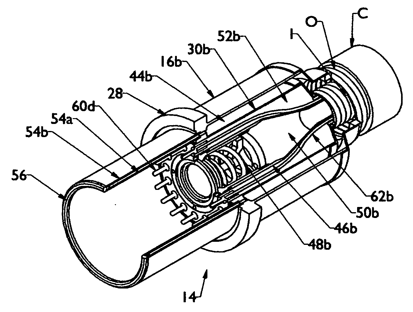
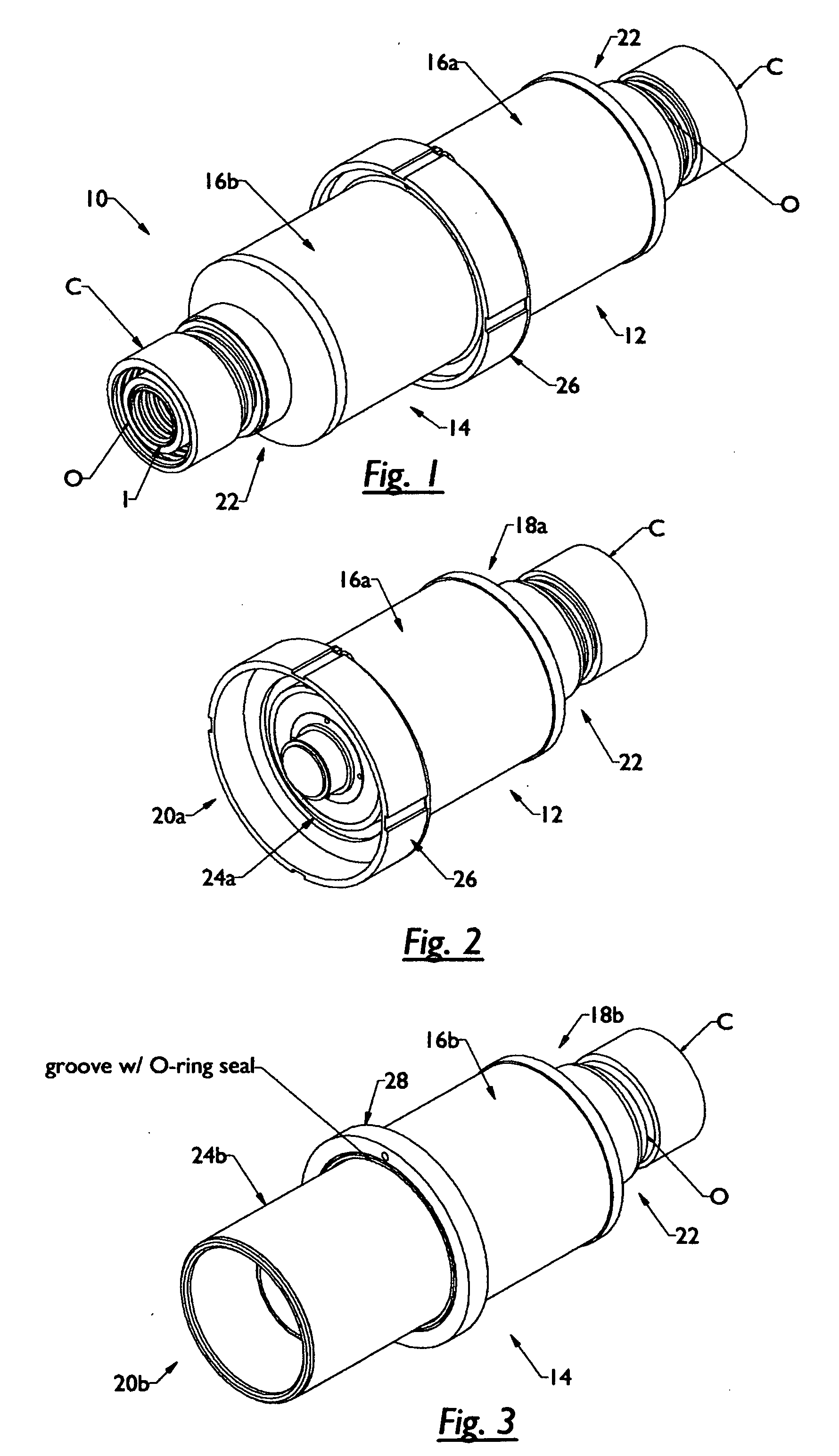
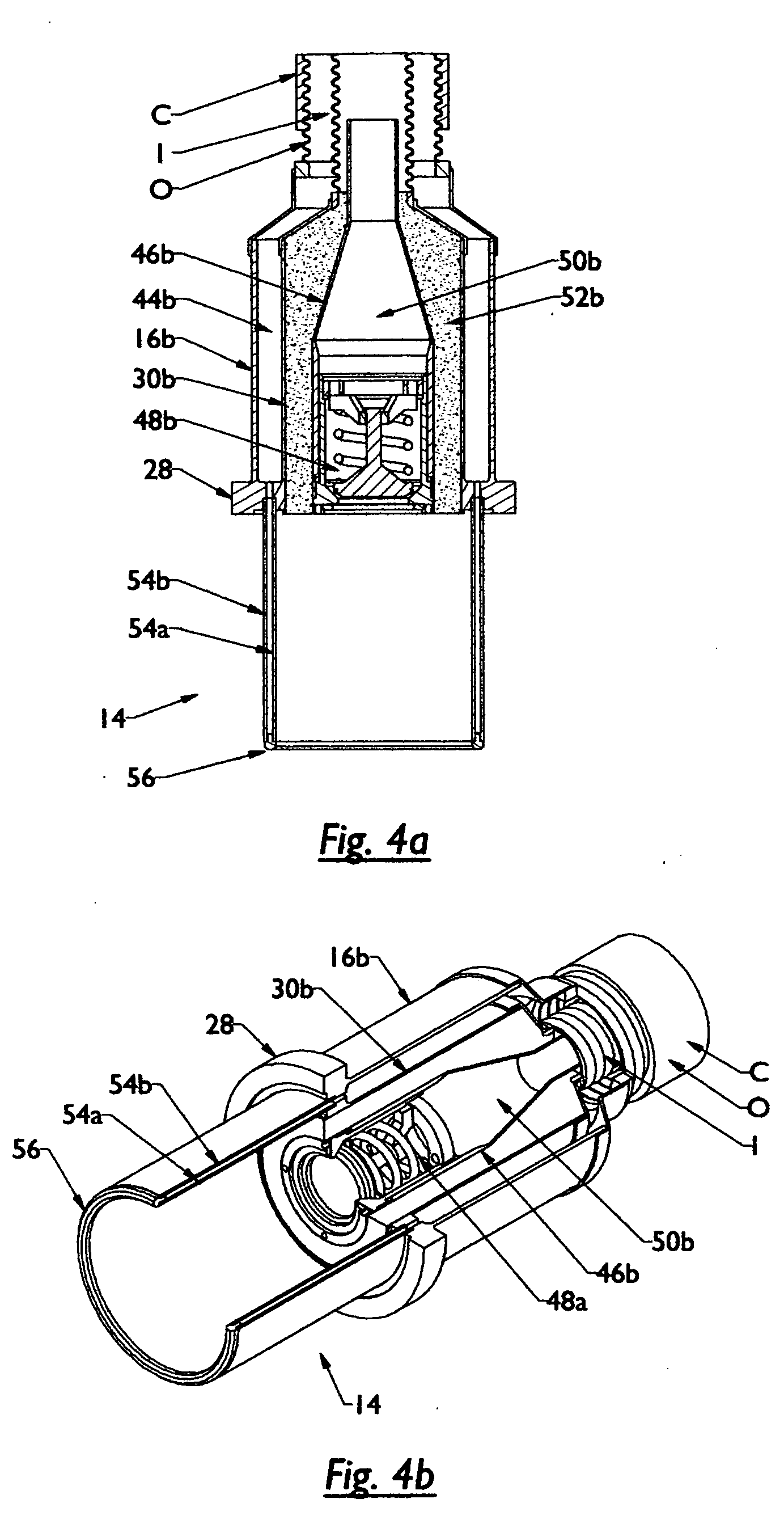
[0043]In order to provide for such a successful connection, the present invention 10, as seen in FIGS. 1-3, comprises a female termination portion 12 (FIGS. 1 and 2) and a male termination portion 14 (FIGS. 1 and 3). The female and male termination portions being adapted to be removably secured to each other. It is noted that shown is the use of female and male connecting means, but it is to be understood by those skilled in the art that other forms can be utilized when mating or connecting the termination portions.
[0044]As seen in these drawings, the female and male termination portions each include an outer shell 16a and 16b, respectively. Each shell member has opposite ends. The ends being 18a and 20a for the female termination portion and 18b and 20b for the male termination portion.
[0045]Extending outwardly from the first end 18a and 18b of each termination portion is a receiving end 22. This receiving end is structured so as to receive and mate with a conventional cryogenic co...
second embodiment
[0066]As shown in this second embodiment, in FIG. 8a, the opposite end can extend beyond the inner sleeve 46a. In essence, as seen in FIGS. 8a, 8b, and 9, the electrical conductor 62b, such as a wire, tape form, or the like is coupled to the electrical connecting element 60a. This electrical conductor 62a extends from the electrical connection element 60a through encapsulated material 52a and to the exterior of the cryogenic guide channel 50a. This will allow for the electrical conductor of the conventional conduit, illustrated, but not labeled, mating with the electrical connection element 60a to the electrical conductor 62a. Such a configuration will ensure electrical communication within the female portion of the coupler of the present invention.
[0067]The male termination portion 14, for this second embodiment is shown in FIGS. 7a, 7b and 9. As with the previous embodiment, this male termination portion will mate with and receive the female termination portion 12 to provide for a...
third embodiment
[0087]The male termination portion 14, for this third embodiment is shown in FIGS. 10a, 10b and 12. As with the previous embodiment, this male termination portion will mate with and receive the female termination portion 12 to provide for a connector that enables fluid flow as well as simultaneous electrical connection. Disconnection of the male termination portion 14 to the female termination portion will prevent fluid flow and will disconnect electrical connection.
[0088]To provide for such a configuration, the male termination portion 14 being substantially the same as the first and second embodiment, thus includes an inner shell 30b having opposite; wherein the first end being designed and configured to include several tubes or conical structures, so as to make a hermetic seal to the end of the inner jacket I of the conventional conduit C.
[0089]A locking means is utilized for locking the male portion to the female portion. Sealing collar 28 is received within the collar receiving...
PUM
 Abstract
Description
Claims
Application Information
 - R&D
- Intellectual Property
- Life Sciences
- Materials
- Tech Scout
- Unparalleled Data Quality
- Higher Quality Content
- 60% Fewer Hallucinations
Browse by: Latest US Patents, China's latest patents, Technical Efficacy Thesaurus, Application Domain, Technology Topic, Popular Technical Reports.
© 2025 PatSnap. All rights reserved.Legal|Privacy policy|Modern Slavery Act Transparency Statement|Sitemap|About US| Contact US: help@patsnap.com


