Device and Method for Stent Graft Fenestration in Situ

a technology of stent graft and in situ grafting, which is applied in the field of intravascular devices and methods, can solve the problems of inconsistent elliptical design of elliptical balloon b>120/b> and the function of anchoring

Inactive Publication Date: 2009-05-14
MEDTRONIC VASCULAR INC
View PDF27 Cites 94 Cited by
  • Summary
  • Abstract
  • Description
  • Claims
  • Application Information

AI Technical Summary

Problems solved by technology

Further, the elliptical design of elliptical balloon 120 is not consistent with an anchoring function.

Method used


Image

  • Device and Method for Stent Graft Fenestration in Situ
  • Device and Method for Stent Graft Fenestration in Situ
  • Device and Method for Stent Graft Fenestration in Situ

Examples


Embodiment Construction

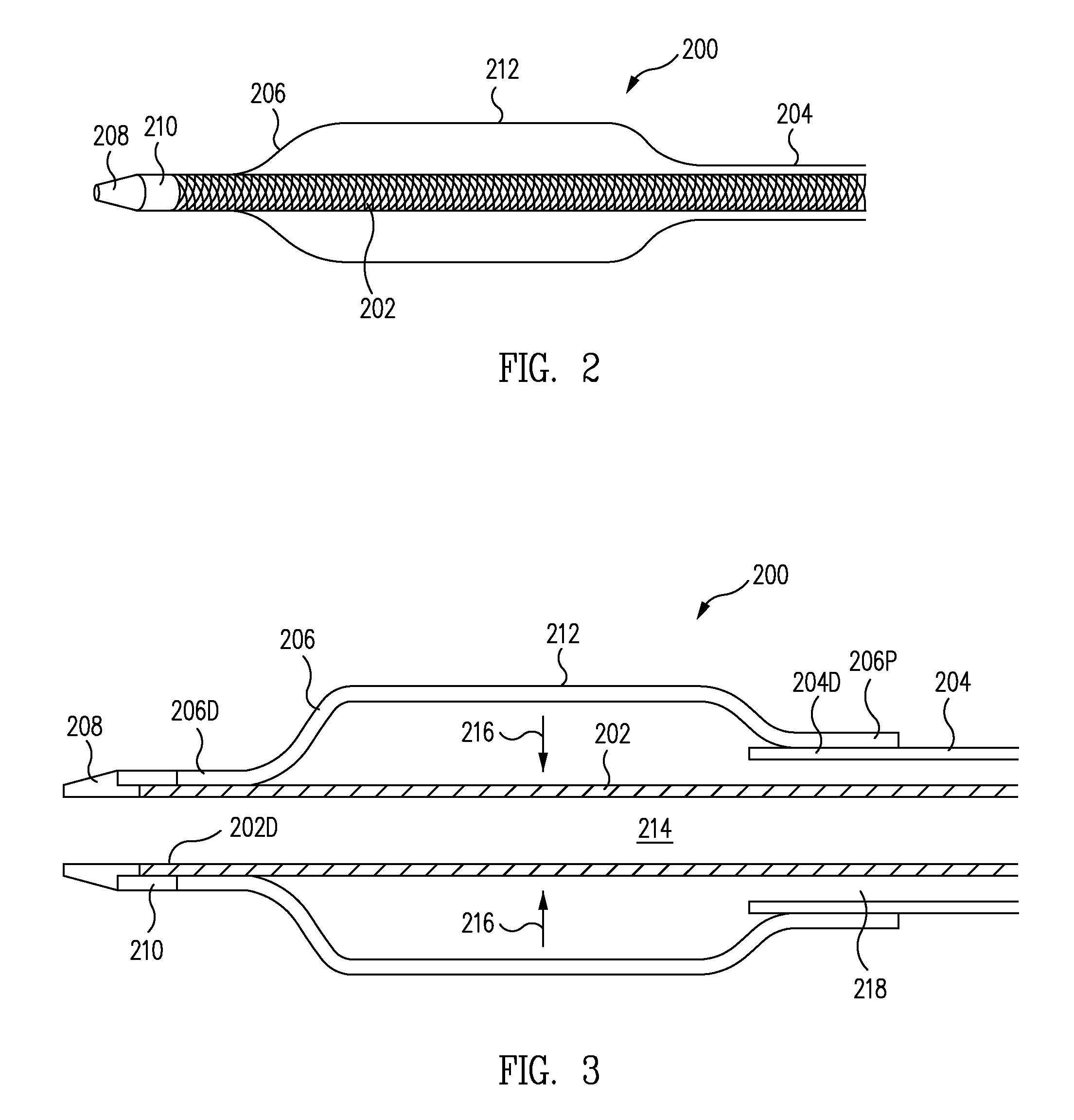
[0038]FIG. 2 is a perspective view of an anchoring balloon catheter 200 in accordance with one embodiment. FIG. 3 is a cross-sectional view of anchoring balloon catheter 200 of FIG. 2. Referring now to FIGS. 2 and 3 together, anchoring balloon catheter 200 includes an inner member 202, an outer member 204, an anchoring balloon 206, a soft tapered tip 208 and a marker band 210.

[0039]Anchoring balloon 206 is a compliant balloon, i.e., has a low modulus of elasticity. In the view of FIGS. 2 and 3, anchoring balloon 206 is illustrated as inflated. As illustrated, anchoring balloon 206 is cylindrical, sometimes called rectangular. More particularly, anchoring balloon 206 has an approximately cylindrical outer surface 212.

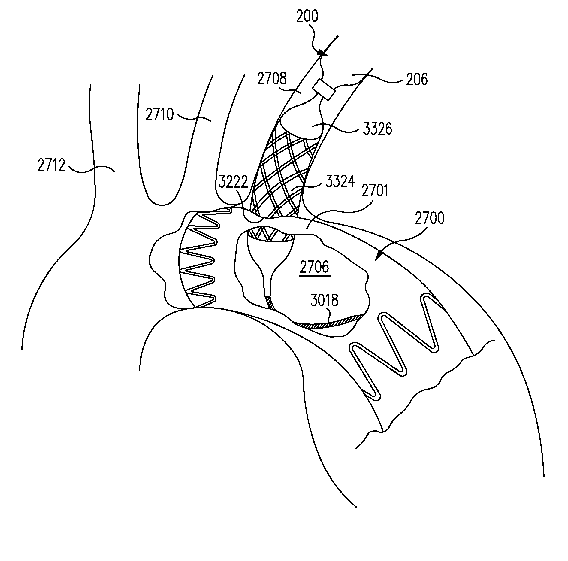
[0040]By forming anchoring balloon 206 as a compliant cylindrical balloon, anchoring balloon 206 anchors anchoring balloon catheter 200 within and aligned with the axis of the branch vessel as discussed further below.

[0041]The distal end of 206D of anchoring balloon 206 ...


PUM


Abstract

An anchoring balloon of an anchoring balloon catheter is advanced through the branch vessel to be adjacent to the main stent graft within a main vessel. The anchoring balloon is inflated to center an inner member of the anchoring balloon catheter within the branch vessel and to anchor the anchoring balloon within the branch vessel. A needle assembly is advanced to pierce the graft material of the main stent graft with a needle forming a needle hole in the graft material. A dilator assembly is advanced to dilate the needle hole with a dilator.

Description

BACKGROUND OF THE INVENTION[0001]1. Field of the Invention[0002]The present invention relates generally to an intra-vascular device and method. More particularly, the present invention relates to a device and method for treatment of intra-vascular diseases.[0003]2. Description of the Related Art[0004]FIG. 1 is a perspective view, partially cutaway, of a needle guiding balloon catheter assembly 100 for fenestrating a main stent graft 102 in accordance with the prior art. Referring now to FIG. 1, an aorta 104 includes an aneurysm 106. Branching off aorta 104 are three branch vessels 108, 110, 112, e.g., the subclavian, the common carotid, and the brachiocephalic trunk.[0005]Main stent graft 102 seals against aorta 104 above and below, e.g., proximally and distally to, aneurysm 106 (only the top of which is shown). Accordingly, fluid flows through the lumen of main stent graft 102 thus bypassing and excluding aneurysm 106.[0006]Due to the variations in the structure and geometry of the...

Claims


Application Information

Patent Timeline
Patent Type & Authority Applications(United States)
IPC IPC(8): A61F2/06A61M29/02A61B17/34A61F2/82
CPCA61B17/3468A61B17/3478A61B2017/22068A61B2017/22069A61B2017/3486A61F2/07A61F2/89A61F2/958A61F2002/061A61F2002/821A61M25/065A61M29/00A61F2/954
Inventor BRUSZEWSKI, WALTERRUST, MATTHEWGREENAN, TREVORMAFI, MASOUMEH
Owner MEDTRONIC VASCULAR INC
Why Eureka
Try Eureka