Fuel injection system for a gas turbine engine

a fuel injection system and gas turbine engine technology, applied in the field of gas turbine engines, can solve the problems of time-consuming assembly operation, high cost of manufacturers, and high cost of precision machining of mating components

Active Publication Date: 2009-05-21
PRATT & WHITNEY CANADA CORP
View PDF61 Cites 7 Cited by
  • Summary
  • Abstract
  • Description
  • Claims
  • Application Information

AI Technical Summary

Benefits of technology

[0005]It is therefore an object of this invention to provide an improved fuel injection system for a gas turbine engine.

Problems solved by technology

In order to achieve a high quality brazing joint, precision machining of the mating components is required which is costly for the manufacturers.
Furthermore, the use of an expensive brazing paste is necessary to carry out the brazing process.
Due to a very small parts size, particularly in smaller gas turbine engines, the assembly operation is time consuming and requires a highly skilled technician to do the work.
Once a nozzle tip is assembled, it is very difficult and often not at all possible to overhaul the nozzle tip or fuel conveying member if necessary.
Consequently, one damaged nozzle tip could be a reason to scrap the nozzle or entire internal manifold.

Method used


Image

  • Fuel injection system for a gas turbine engine
  • Fuel injection system for a gas turbine engine
  • Fuel injection system for a gas turbine engine

Examples


Embodiment Construction

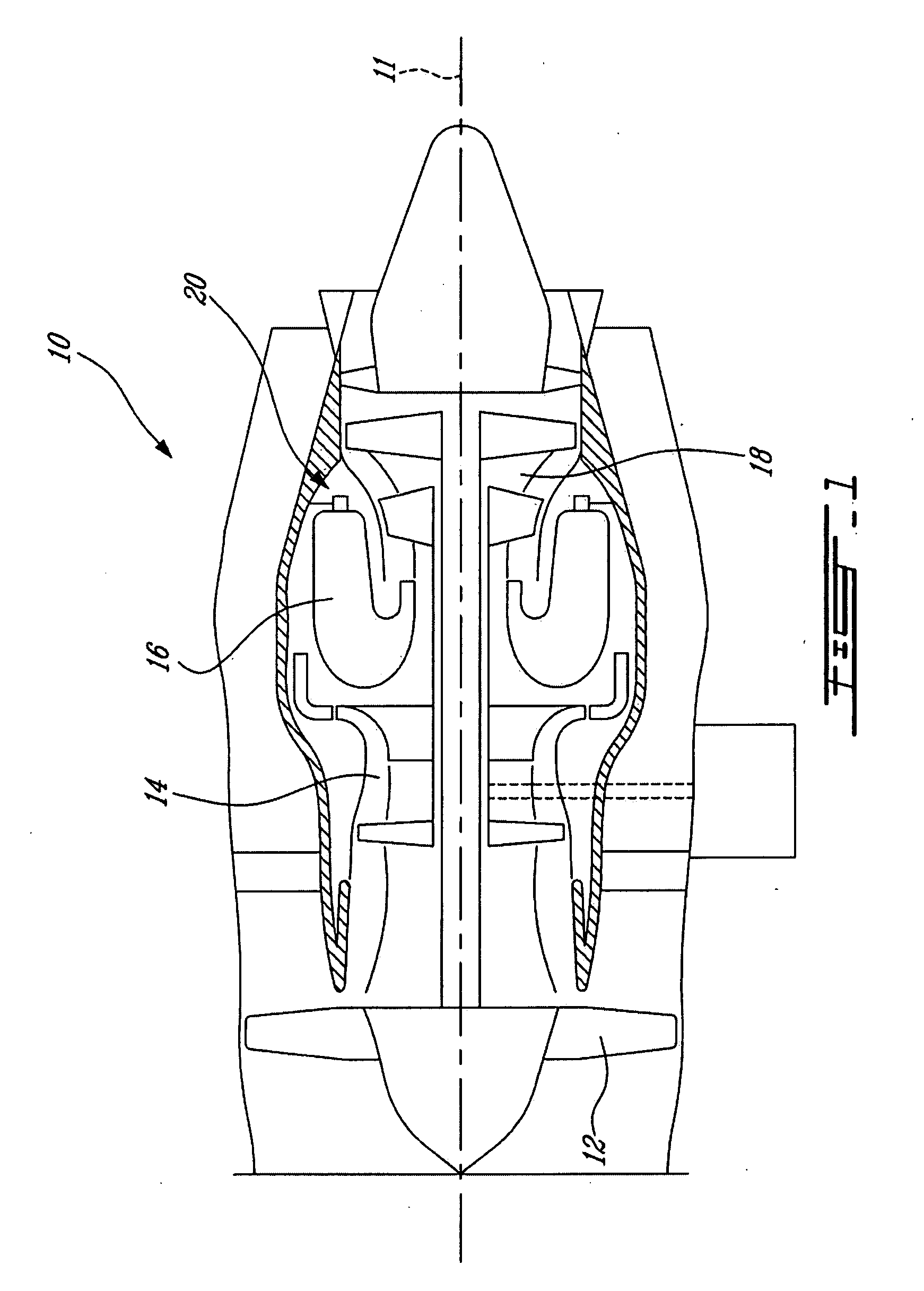
[0015]FIG. 1 illustrates a gas turbine engine 10 of a type preferably provided for use in subsonic flight, generally comprising in serial flow communication a fan 12 through which ambient air is propelled, a multistage compressor 14 for pressurizing the air, a combustor 16 in which the compressed air is mixed with fuel and ignited for generating an annular stream of hot combustion gases, and a turbine section 18 for extracting energy from the combustion gases.

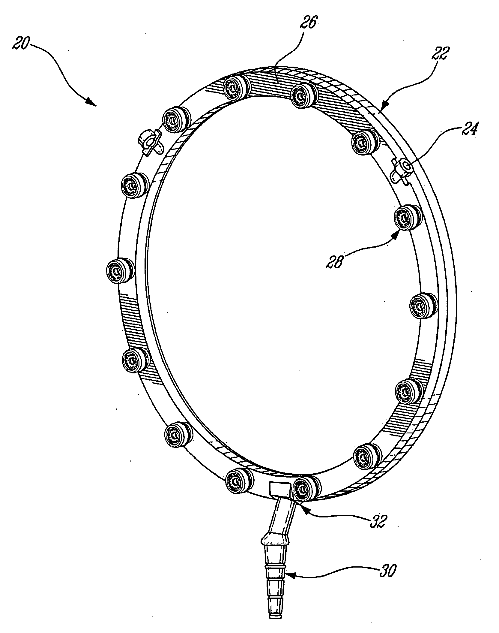
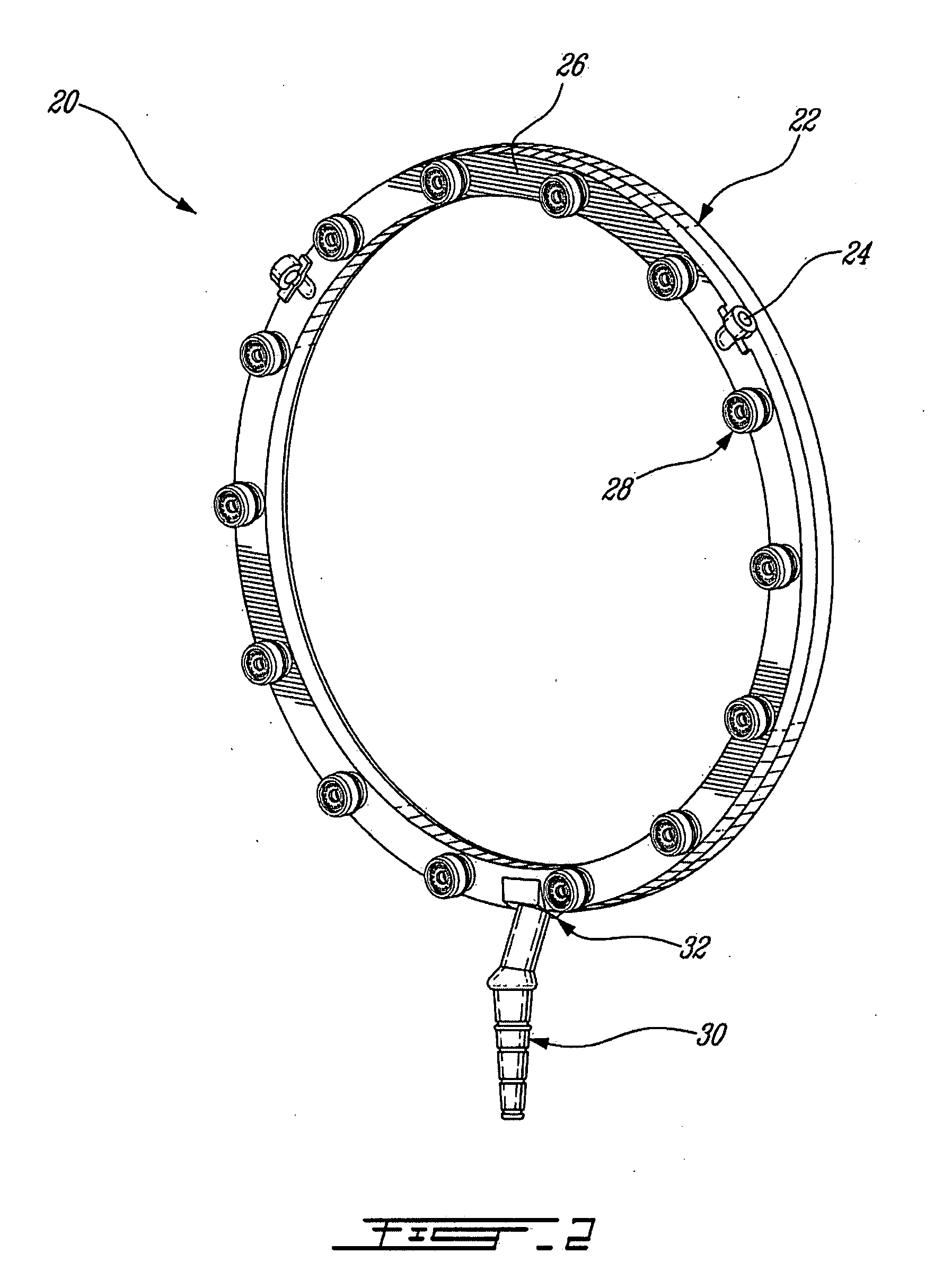
[0016]Fuel is injected into the combustor 16 of the gas turbine engine 10 by a fuel injection system 20 which is connected in fluid flow communication with a fuel source (not shown) and is operable to inject fuel into the combustor 16 for mixing with the compressed air from the compressor 14 and ignition of the resultant mixture. The fan 12, compressor 14, combustor 16, and turbine 18 are preferably all concentric about a common central longitudinal axis 11 of the gas turbine engine 10.

[0017]Referring to FIG. 2, the fuel inject...


PUM


Abstract

A fuel injection system comprises a fuel conveying member and a nozzle tip assembly threadably engaged thereto. A pair of sealing elements is engaged in a fuel passage between the fuel conveying member and the nozzle tip for sealing the junction therebetween. The pair of sealing elements includes a first and a second sealing element located proximate each other and having different cross-sectional shape.

Description

CROSS-REFERENCE TO RELATED APPLICATIONS[0001]The is a continuation-in-part of U.S. patent application Ser. No. 11 / 513,030 filed Aug. 31, 2006, the entire contents of which are incorporated herein by reference.TECHNICAL FIELD[0002]The invention relates generally to a gas turbine engine and, more particularly, to an improved fuel injection system for a gas turbine engine.BACKGROUND OF THE ART[0003]A gas turbine engine may have an internal manifold with attached fuel nozzle tips. Often, a fastening / sealing method such as a brazing process is utilized in order to achieve a rigid joint between the fuel conveying member and the nozzle tips that does not introduce a leak during engine operation. In order to achieve a high quality brazing joint, precision machining of the mating components is required which is costly for the manufacturers. Furthermore, the use of an expensive brazing paste is necessary to carry out the brazing process. Due to a very small parts size, particularly in smaller...

Claims


Application Information

Patent Timeline
Patent Type & Authority Applications(United States)
IPC IPC(8): F02C7/22
CPCF02C7/22F23D11/383F05D2250/311F05D2240/55F05D2250/70F05D2240/35
Inventor PATEL, BHAWAN B.MORENKO, OLEGRUDRAPATNA, NAGARAJA
Owner PRATT & WHITNEY CANADA CORP
Why Eureka
Try Eureka