
Methods for making optical fiber preforms and microstructured optical fibers

a technology of microstructured optical fibers and preforms, applied in the direction of manufacturing tools, glass deposition burners, other domestic articles, etc., can solve the problems of affecting dramatically the attenuation of fibers, reshaping or deformation, and low productivity

Inactive Publication Date: 2009-05-21
CORNING INC
View PDF10 Cites 47 Cited by
  • Summary
  • Abstract
  • Description
  • Claims
  • Application Information

AI Technical Summary

Benefits of technology

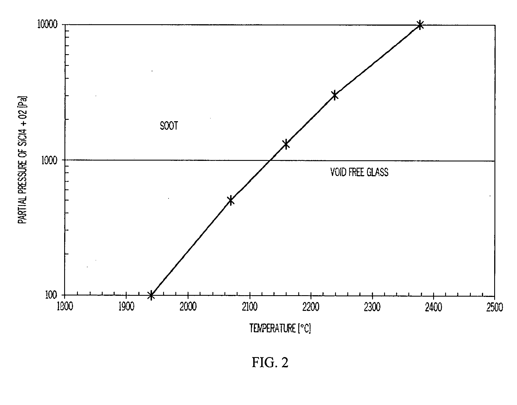
[0008]Another aspect of the present invention relates to a method of making an optical fiber. The method may comprise forming an optical fiber preform by flowing a carrier gas comprising silica glass precursors inside a substrate tube. A plasma may be applied to the substrate tube at a first set of plasma temperature/precursor pressure parameters P1 causing a first layer of silica glass to be deposited inside the substrate tube. A plasma may then be applied to the substrate tube at a second set of plasma temperature/precursor pressure parameters P2 causing a second layer of silica glass to be deposited inside the substrate tube. The first and second parameters P1 and P2 may be selected such that the first layer of silica glass ...

Problems solved by technology

There are several disadvantages to the stack and draw method.
The awkwardness of assembling hundreds of very thin canes (defined by rods or tubes), as well as the possible presence of interstitial cavities when stacking and drawing cylindrical canes, may affect dramatically the fiber attenuation by introducing soluble and particulate impurities, undesired interfaces and inducing a reshaping or deformation of the starting holes.
Moreover, the relatively low productivity and high cost make this method not much suitable for industrial production.

Method used


Image

  • Methods for making optical fiber preforms and microstructured optical fibers
  • Methods for making optical fiber preforms and microstructured optical fibers
  • Methods for making optical fiber preforms and microstructured optical fibers

Examples


Embodiment Construction

[0018]The methods of the present invention utilize plasma chemical vapor deposition (PCVD) techniques to form optical fiber preforms having a non-periodic distribution of voids. The resultant preform is used to produce a microstructured optical fiber. At least a portion of the microstructured optical fiber is formed from a region of the optical fiber preform comprising voids such that at least a portion of the microstructured optical fiber has a non-periodic distribution of voids extending axially along the microstructured optical fiber.

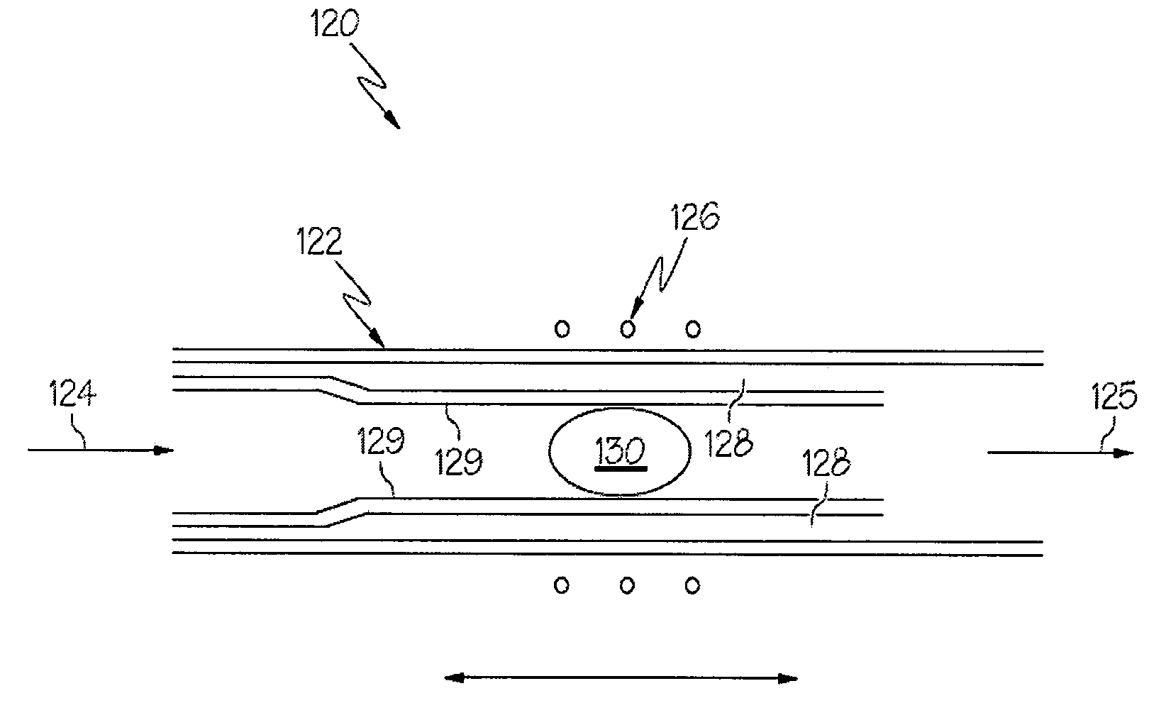
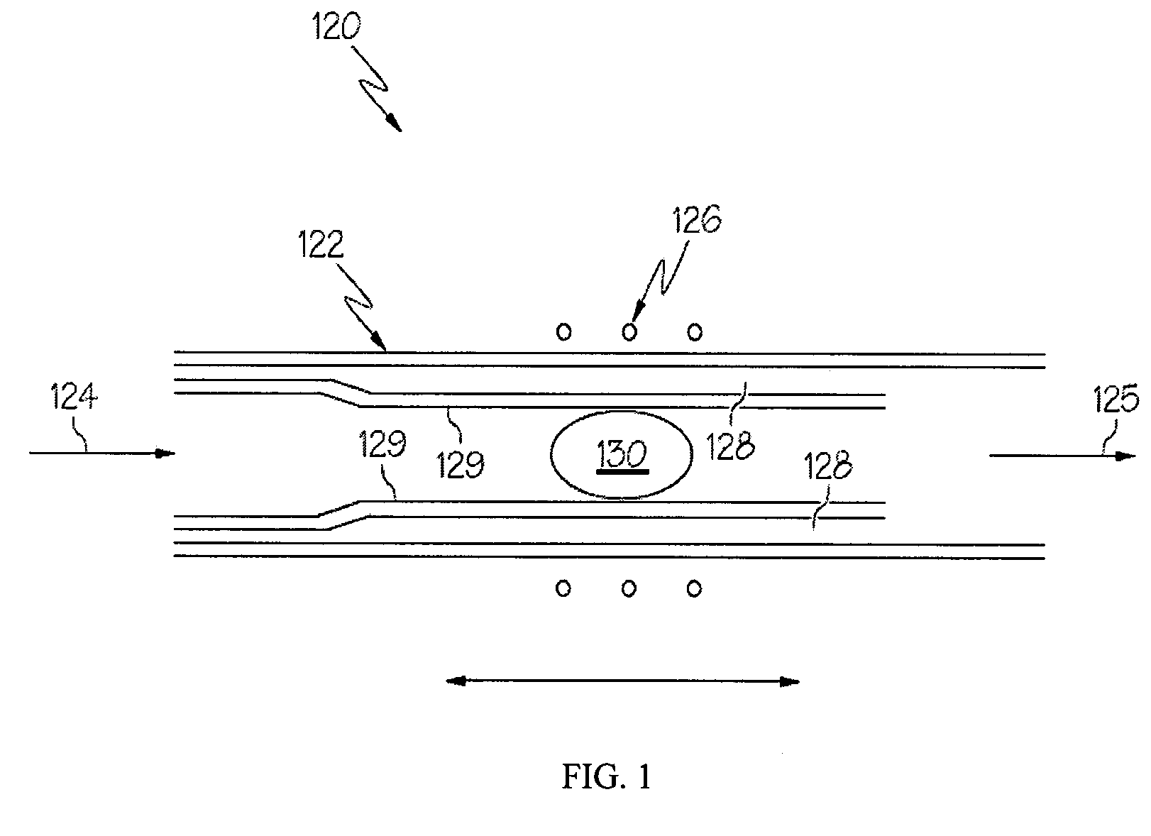
[0019]FIG. 1 is a schematic diagram of a PCVD operation 120 for making an optical fiber preform in accordance with the present invention. As shown in FIG. 1, a substrate tube 122 is positioned in an RF coil 126 or another suitable plasma excitation source. A heat source (not shown), such as a furnace, may be used in conjunction with the RF coil to initially heat the substrate tube 122. The substrate tube 122 may comprise silica glass or silica glass ...


PUM

PropertyMeasurementUnit
Temperatureaaaaaaaaaa

Abstract

A method of making an optical fiber preform includes depositing silica glass on the inside of a tube substrate via a plasma chemical vapor deposition (PCVD) operation. The parameters of the PCVD operation are controlled such that the silica glass deposited on the interior of the tube substrate contains a non-periodic array of voids in a cladding region of the optical fiber preform. The optical fiber preform may be used to produce an optical fiber having a core and a void containing cladding. The core of the optical fiber has a first index of refraction and the cladding has a second index of refraction less than that of the core.

Description

CROSS-REFERENCE TO RELATED APPLICATIONS[0001]This application claims the benefit of, and priority to U.S. Provisional Patent Application filed on Nov. 15, 2007 entitled, “Methods for Making Optical Fiber Preforms and Microstructured Optical Fibers”, the content of which is relied upon and incorporated herein by reference in its entirety.BACKGROUND OF THE INVENTION[0002]1. Field of the Invention[0003]The present invention relates generally to methods for making optical fiber preforms and optical fibers and, more specifically, to methods of making optical fiber preforms containing voids and microstructured optical fibers.[0004]2. Technical Background[0005]Optical fibers formed of glass materials have been in commercial use for more than two decades. Although such optical fibers have represented a quantum leap forward in the field of telecommunications, work on alternative optical fiber designs continues. One promising type of alternative optical fiber is the microstructured optical fi...

Claims


Application Information

Patent Timeline
IPC IPC(8): C03B37/018
CPCC03B37/0183C03B37/01861C03B37/02781C03B2207/70C03B2201/31C03B2203/14C03B2203/42C03B2201/12
Inventor BOOKBINDER, DANA CRAIGDESORCIE, ROBERT BRETTTANDON, PUSHKAR
Owner CORNING INC
Learn More