Filling Level Sensor for Short Measuring Distances

a filling level and measurement distance technology, applied in waveguide horns, instruments, and reradiation, etc., can solve the problems of reducing the measuring sensitivity of minor reflections from the material surface, reducing the stability of the antenna system, and difficult or even impossible for the sensor to detect echoes. the effect of simple manufactur

Inactive Publication Date: 2009-05-21
VEGA GRIESHABER GMBH & CO
View PDF9 Cites 11 Cited by
  • Summary
  • Abstract
  • Description
  • Claims
  • Application Information

AI Technical Summary

Benefits of technology

[0024]According to another exemplary embodiment of the present invention, the antenna system is realized in one piece. The stability of the antenna system may be increased in this fashion.
[0025]In ad

Problems solved by technology

Due to their design, conventional filling level measuring devices have an inferior accuracy at shorter distances from the material surface (up to approximately 1.5 m) than at distances of more than 2 m from the material surface.
These reflections extend into the measuring range of the sensor and cause interferences with a reflection or an echo of a material surface in this measuring range or even reduce the measuring sensitivity for minor reflections from the material surface.
This is also referred to as

Method used


Image

  • Filling Level Sensor for Short Measuring Distances
  • Filling Level Sensor for Short Measuring Distances
  • Filling Level Sensor for Short Measuring Distances

Examples


Embodiment Construction

[0046]The illustrations shown in the figures are purely schematic and not drawn true-to-scale.

[0047]In the following description of the figures, the same reference symbols are used for identical or similar elements.

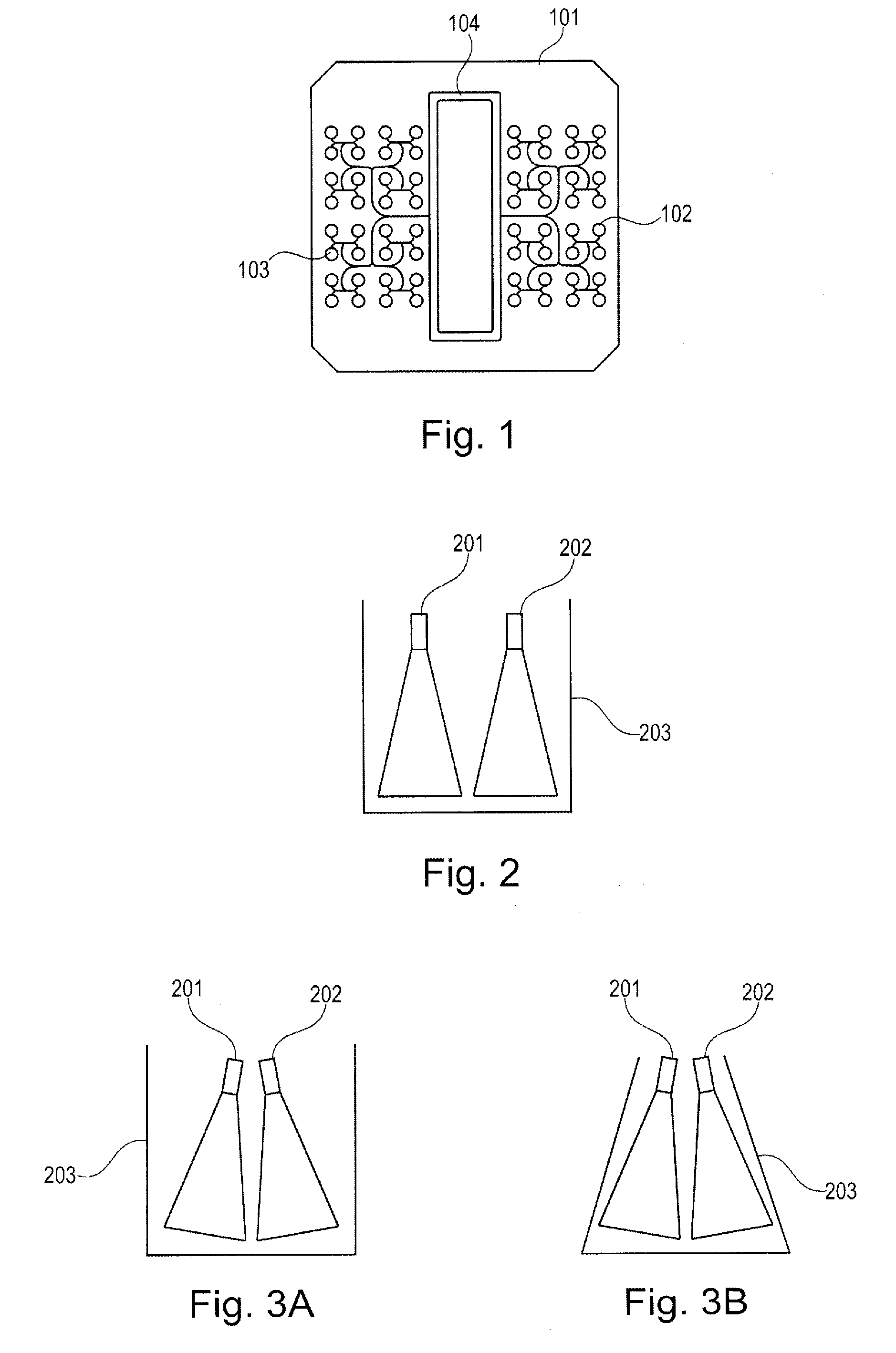
[0048]FIG. 1 shows a radar sensor with separate planar antennas 102, 103 for the transmitter and the receiver. The planar antennas 102, 103 are arranged on a printed circuit board 101. An electronics module 104 is also provided.

[0049]Since the planar antennas 102, 103 and the microwave circuitry 104 are jointly arranged on the substrate 101, the process temperature inside the container is clearly limited because the electronic components are subjected to the full temperature of the container.

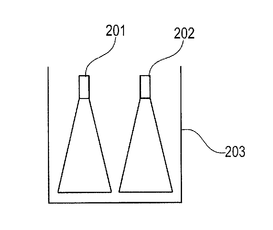
[0050]FIG. 2 shows an antenna system with a first horn antenna 201 and a second horn antenna 202 that are arranged adjacent to one another in a common housing 203. In this case, the cross-sectional surfaces of the antenna horns are realized, for example, round or elliptical.

[0051]FIG....


PUM


Abstract

A filling level sensor for a short distance measurement includes a first antenna transmitting a transmission signal to a material surface; a second antenna receiving a reception signal reflected by the material surface; and a common outer enclosure enclosing the first antenna and the second antenna.

Description

PRIORITY CLAIM[0001]This application claims the benefit of the filing date of European Patent Application Serial No. 07 120 998.5 filed Nov. 19, 2007 and U.S. Provisional Patent Application Ser. No. 60 / 988,956 filed Nov. 19, 2007, the disclosure of which applications is hereby incorporated herein by reference.FIELD OF INVENTION[0002]The present invention pertains to filling level measurements. The present invention specifically pertains to a filling level sensor for short distance measurements, to an antenna system for a filling level sensor, to the utilization of a filling level sensor for filling level measurements and to the utilization of an antenna system for filling level measurements.BACKGROUND INFORMATION[0003]Due to their design, conventional filling level measuring devices have an inferior accuracy at shorter distances from the material surface (up to approximately 1.5 m) than at distances of more than 2 m from the material surface. These inaccuracies may be caused, for ex...

Claims


Application Information

Patent Timeline
IPC IPC(8): G01S13/08G01F23/00
CPCG01F23/284G01S7/03H01Q13/02H01Q1/225H01Q1/42G01S13/88
Inventor FEHRENBACH, JOSEFGRIESSBAUM, KARLKIENZLE, KLAUSSCHULTHEISS, DANIEL
Owner VEGA GRIESHABER GMBH & CO
Why Eureka
Try Eureka