Light guide plate, surface light source device, and liquid crystal display device

Inactive Publication Date: 2009-05-21
SUMITOMO CHEM CO LTD
View PDF24 Cites 69 Cited by
  • Summary
  • Abstract
  • Description
  • Claims
  • Application Information

AI Technical Summary

Benefits of technology

[0030]In this configuration, the light output from the light source section possessed by the surface light source device is made incident inside the light guide plate main body from the first surface of the light guide plate main body possessed by the light guide plate. Furthermore, the light made incident inside the light guide plate main body propagates toward the third surface. At this time, since the diffraction grating section is arranged on the second surface, the light propagating inside the light guide plate main body can be extracted from the second surface side. Additionally, since the interval Λ of the diffraction grating section satisfies the above-described relationship with respect to the wavelength λ possessed by the light, the emission angle from the light guide plate can be controlled. Furthermore, the refractive index of the grating constituting the diffraction grating se

Problems solved by technology

Accordingly, emission an

Method used


Image

  • Light guide plate, surface light source device, and liquid crystal display device
  • Light guide plate, surface light source device, and liquid crystal display device
  • Light guide plate, surface light source device, and liquid crystal display device

Examples


Example

First Embodiment

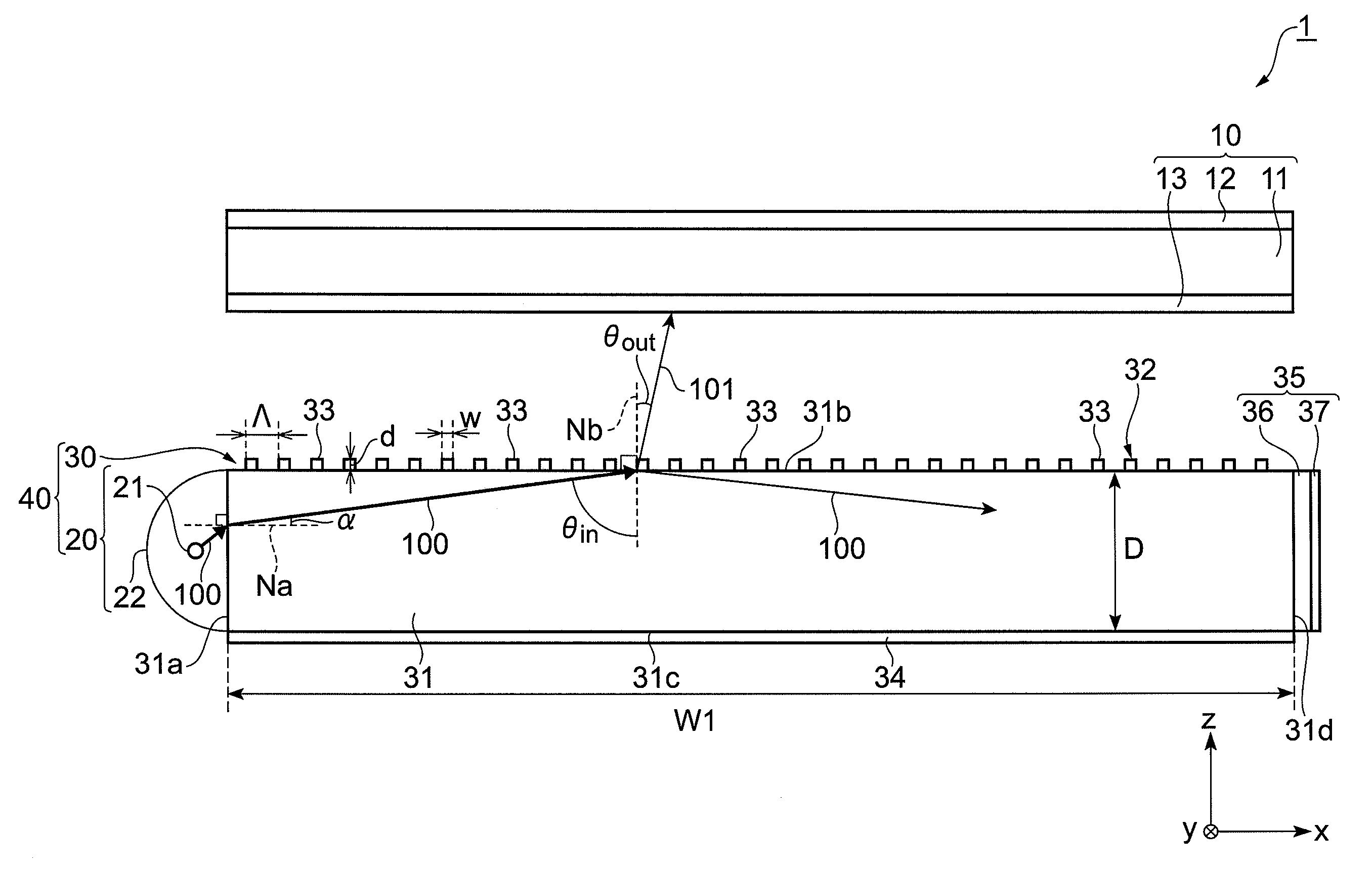
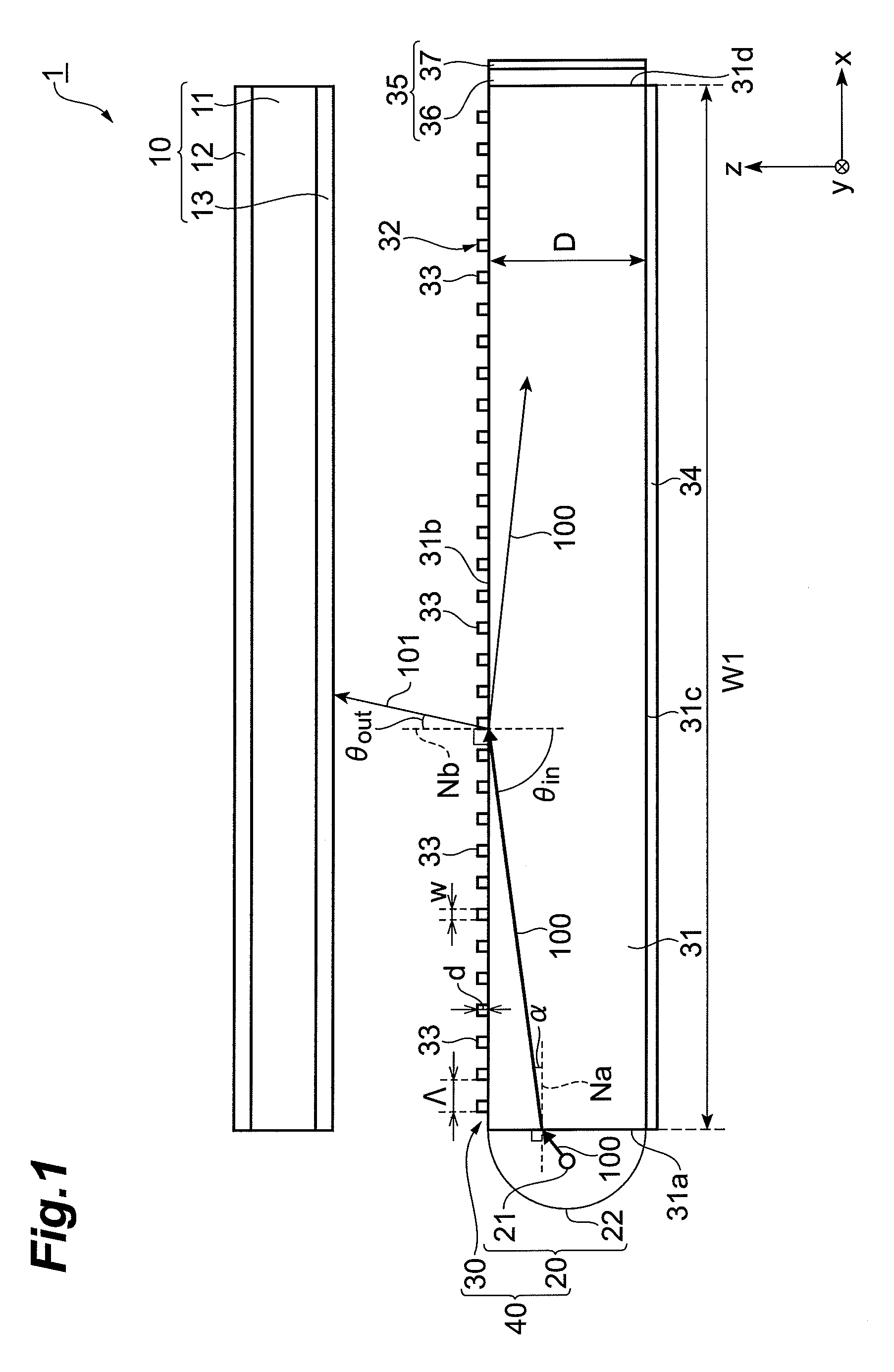
[0049]FIG. 1 is a side view schematically showing a configuration of one embodiment of the liquid crystal display device according to the present invention. A liquid crystal display device 1 includes a liquid crystal display element 10, and a surface light source device 40 being one embodiment of the surface light source device according to the present invention, and is preferably applied to a device that can be made mobile such as a laptop computer or the like. In the following explanation, as shown in FIG. 1, an arrangement direction between the surface light source device 40 and the liquid crystal display device 10 can be called the z axis direction, and 2 directions crossing at roughly right angles with the z axis direction can be called the x axis direction and the y axis direction.

[0050]The liquid crystal display device 10 is configured by laminating polarizing plates 12, 13 on upper / lower surfaces of a liquid crystal cell 11. In the following explanation, a la...

Example

Second Embodiment

[0134]FIG. 15 is a side view schematically showing a configuration of another embodiment of the light guide plate according to the present invention. A light guide plate 30A differs from the light guide plate 30 in a point that a diffraction grating section 32A is provided instead of the diffraction grating section 32. A configuration of the light guide plate 30A except for this different point is the same as the configuration of the light guide plate 30 shown in FIG. 1 and FIG. 2. This light guide plate 30A, as with the case of the light guide plate 30, is preferably utilized for the liquid crystal display device 1, and the surface light source device 40 applied to it. Hereinafter, regarding the light guide plate 30A, the configuration of the diffraction grating section 32A which is a different point with the light guide plate 30 is mainly explained.

[0135]The diffraction grating section 32A is configured in such a manner that the grating 33 consisting of a dielectr...

Example

Third Embodiment

[0140]FIG. 16 is a side view schematically showing a configuration of still another embodiment of the light guide plate according to the present invention. The light guide plate 30B mainly differs in configuration from the light guide plate 30 from the point that the diffraction grating section 32B is provided instead of the diffraction grating section 32. A configuration of the light guide plate 30B except for this different point is the same as a configuration of the light guide plate 30. Furthermore, in FIG. 16, descriptions of the reflector 34 and the polarization converting element 35 are omitted. This light guide plate 30B, as with the case of the light guide plate 30, can be preferably utilized to the liquid crystal display device 1, and the surface light source device 40 applied to it. Hereinafter, regarding the light guide plate 30B, the configuration of the diffraction grating section 32B being the different point with the light guide plate 30 is mainly exp...


PUM


Abstract

The present invention provides a light guide plate which can process in polarization separation, and emit a light in a desirable direction, a surface light source device, and a liquid crystal display device. A light guide plate 30 includes a light guide plate main body 31 including a first surface 31a on which a light 100 output from a light source section 20 is made incident, a second surface 31b adjacent to the first surface, a third surface 31d which faces the first surface, and is adjacent to the second surface, and a fourth surface which faces the second surface, and is adjacent to the third surface, and a diffraction grating section 32 arranged on the second surface 31b wherein; the diffraction grating section 32 is configured in such a way that a plurality of gratings 33 consisting of a dielectric is arranged in parallel at an interval Λ along a predetermined direction facing from the first surface to the third surface, wherein; when a wavelength of a visible region possessed by a light 100 is set to be λ, the interval Λ satisfies 1≧Λ/λ≧0.5, and when a refractive index of the light guide plate main body 31 is set to be ns, and a refractive index of the grating 33 is set to be ng, the refractive index ng satisfies ng-ns≧0.15.

Description

BACKGROUND OF THE INVENTION[0001]1. Field of the Invention[0002]The present invention relates to a light guide plate, a surface light source device, and a liquid crystal display device.[0003]2. Related Background of the Invention[0004]As a liquid crystal display device such as a liquid crystal display or the like, a configuration, in which a liquid crystal display section formed by arranging a pair of polarizing plates in both of the upper and lower surfaces of liquid crystal display element such as a liquid crystal cell or the like, is provided, furthermore, a surface light source device used for a backlight is arranged on a rear surface side (lower side) of the liquid crystal display section is known. In most liquid crystal display devices, especially, the liquid crystal display device utilized for a mobile device such as a laptop personal computer or the like, an edge light type is adopted as the surface light source device from a point of view such as a purpose of being made thi...

Claims


Application Information

Patent Timeline
IPC IPC(8): G02F1/13357G02B27/44F21V8/00
CPCG02B6/0035G02B6/00G02F1/1335
Inventor KIM, KIMANKUBOTA, MASAAKI
Owner SUMITOMO CHEM CO LTD
Why Eureka
Try Eureka