
Vibration type microinjection device

a micro-injection device and vibration-type technology, which is applied in the direction of biomass after-treatment, generators/motors, instruments, etc., can solve the problems of difficult precise operation of the micro-pipette, and the difficulty of the bent tip vibrating the tip in its longitudinal direction

Active Publication Date: 2009-05-21
MIYAWAKI FUJIO
View PDF4 Cites 9 Cited by
  • Summary
  • Abstract
  • Description
  • Claims
  • Application Information

AI Technical Summary

Benefits of technology

[0008]In view of the above problems, the present invention provides a vibration type microinjection device capable of making smooth piercing to membranes of different properties such as a zona pellucida, a cell membrane and a nuclear membrane included in a fertilized egg with high accuracy and efficiency.
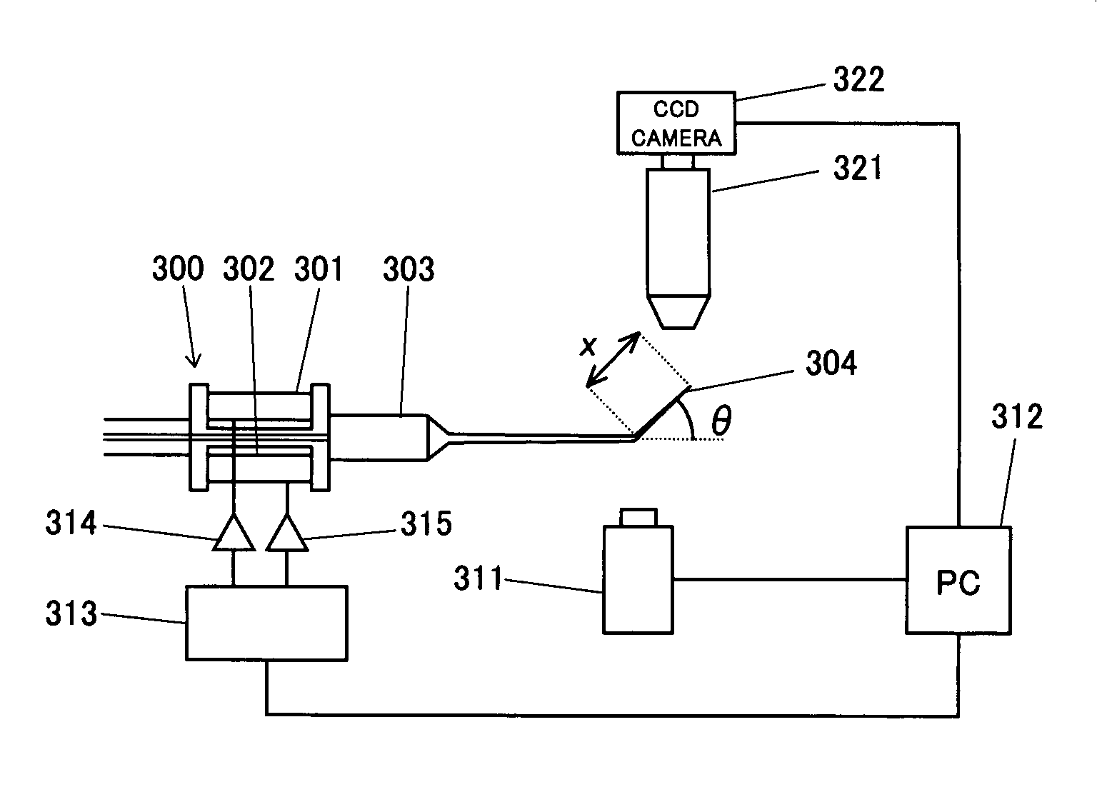
[0026][16] In the vibration type microinjection device described in the above [14] or [15], an imaging device 311 is provided to take image of the bend 304 at the tip of the micropipette 303, image information from the imaging device 311 is taken into a computer 312, and the signal control device 313 is controlled with the computer 312 according to the information about position and angle of the bend 304 at the tip of the micropipette 303 detected by the image analysis to drive each of the plurality of piezoelectric actuators 301, 302, thereby enabling automatic setting of amplitudes, frequencies and phases of the vibrations given to the tip of the micropipette 303 corresponding to the position and angle of the bend 304 at the tip of the micropipette 303.
[0027][17] In the vibration type microinjection device described in the above [16], the vibration type microinjection device comprises an imaging device 311 to take image of the bend 304 at the tip of the micropipette 303; and an imaging device 322 to detect a fertilized egg and the tip of the micropipette 303, wherein image information from the imaging devices 311, 322 are taken into a computer 312, the signal control device 313 is controlled with the computer 312 according to the information about position and angle of the bend 304 at the tip of the micropipette 303 detected by the image analysis and the detected information on the fertilized egg and the tip of the micropipette 303 to drive each of the plurality of piezoelectric actuators 301, 302, thereby enabling detection of positions of the fertilized egg and the tip of the micropipette 303 and automatic control of the vibrations given to the micropipette 303.

Problems solved by technology

Furthermore, in the conventional method as disclosed in the above patent document 5, a precise operation of the micropipette was difficult because of the bent tip of the micropipette.
Moreover, such micropipette having a bent tip has a difficulty in vibrating the tip in its longitudinal direction.

Method used


Image

  • Vibration type microinjection device
  • Vibration type microinjection device
  • Vibration type microinjection device

Examples


embodiments

[0053]Embodiments of the present invention are described in detail in the following.

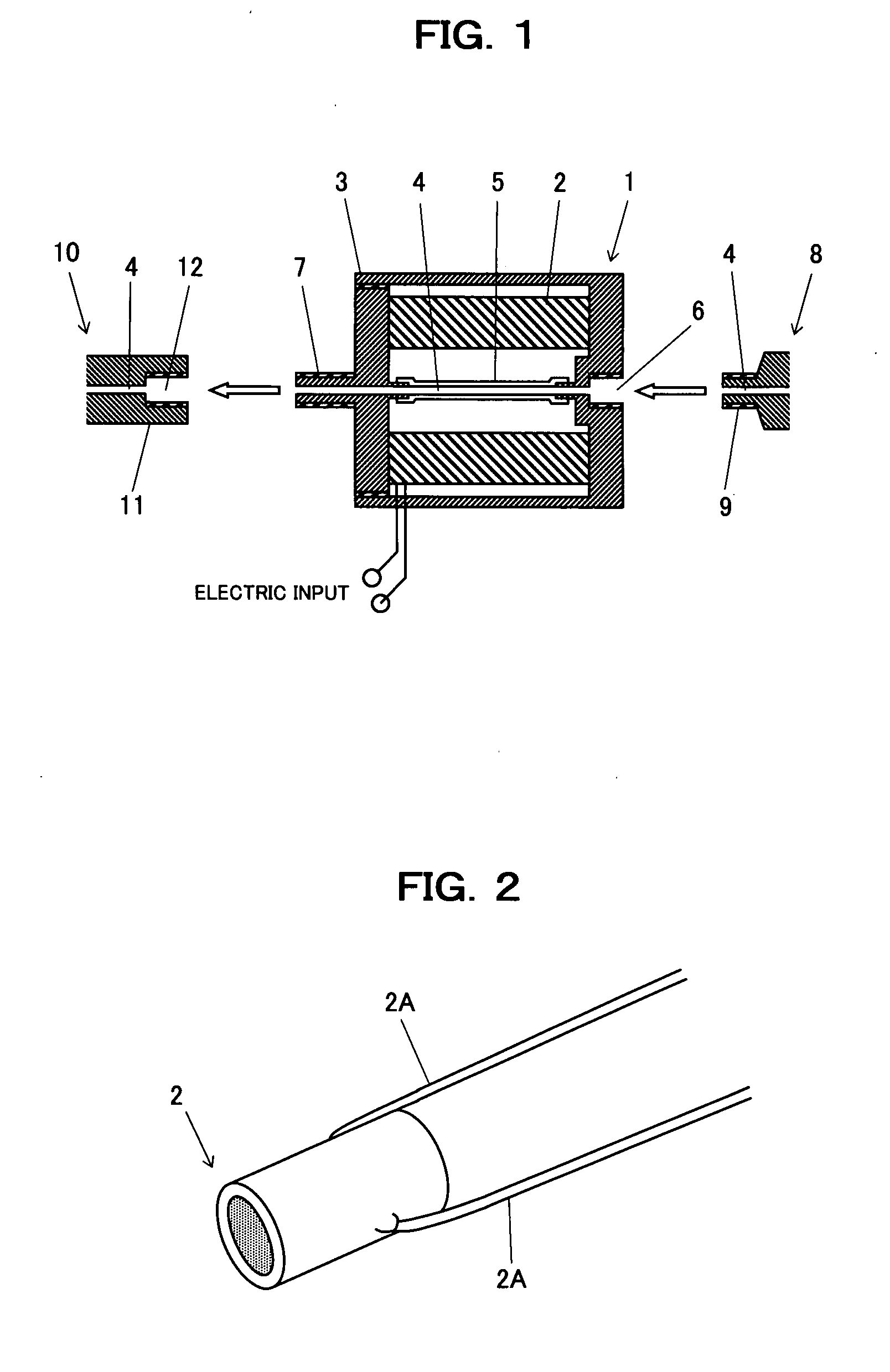
[0054]FIG. 1 is a schematic diagram of a structure of a vibrator of a vibration type microinjection device in accordance with the first embodiment of the present invention, and FIG. 2 is a perspective view of a piezoelectric actuator of the vibration type microinjection device.

[0055]In these figures, 1 is a vibrator comprising a piezoelectric actuator 2 (such as a cylindrical multilayer piezoelectric actuator as shown in FIG. 2) and a housing 3 made of elastically deformable material (such as duralumin) which houses the piezoelectric actuator. This housing 3 has a Teflon™-tube 5 with a narrow path 4 formed at the center. At one end of the housing 3, a fitting concave 6 is formed to be fitted with the base part of the micropipette 8, and at the other end of the housing 3, a fitting convex 7 is formed to fit an injection controller part 10. Besides, on the base part of the micropipette 8, a fitting con...


PUM


Abstract

A vibration type microinjection device capable of ensuring smooth piercing of membranes having different properties such as a zona pellucida, a cell membrane and a nuclear membrane included in a fertilized egg with high accuracy and efficiency is provided.A vibration type microinjection device comprises a vibrator (28) which is connected in series with a micropipette (8) and which has a piezoelectric actuator (29) installed in a housing, and a signal control device (21) for controlling an electric signal applied to the piezoelectric actuator (29), wherein vibration is applied in the longitudinal direction of the micropipette (8) via the vibrator (28) by inputting an electric signal to the piezoelectric actuator (29). By such configuration, smooth piercing of membranes having different properties such as a zona pellucida, a cell membrane and nuclear membrane included in a fertilized egg is realized with high accuracy and efficiency.

Description

TECHNICAL FIELD[0001]The present invention relates to a vibration type microinjection device.BACKGROUND ART[0002]Conventionally in this field, a micro movement device using a piezoelectric element (See Patent Document 1 below.), a micro manipulator using a driving force generator due to the piezoelectric element (See Patent Document 2 below.), and a microinjection device using the driving force generator due to the piezoelectric element (See Patent Document 3 below.) have been proposed. Furthermore, a method of piercing a membrane has been proposed (See Patent Document 4 below.). The method comprises the steps of bringing a membrane denaturing material, which undergoes a membrane denaturation reaction induced by a stimulus, into contact with a part of a membrane to be pierced or close thereto; stimulating the membrane denaturing material so as to denature the membrane; and piercing the membrane by using a membrane breaking material. Moreover, a microinjection device using a micropip...

Claims


Application Information

Patent Timeline
IPC IPC(8): C12M1/26G01N1/14H01L41/09
CPCC12M35/00
Inventor MIYAWAKI, FUJIOKOBAYASHI, KENJIHASEGAWA, JUN
Owner MIYAWAKI FUJIO
Learn More