Radio-frequency communication device

a radio frequency communication and radio frequency technology, applied in the direction of transmission, transmission monitoring, instruments, etc., can solve the problems of insufficient amplifying effect of amplifiers, inability of amplifiers to provide sufficient amplifying effects, and inability to adequately amplify reply signals from radio-frequency tags, etc., to achieve accurate detection of received signal strength, and accurate detection of cancel signal strength

Active Publication Date: 2009-05-21
BROTHER KOGYO KK
View PDF8 Cites 56 Cited by
  • Summary
  • Abstract
  • Description
  • Claims
  • Application Information

AI Technical Summary

Benefits of technology

[0020]As described above, the first invention relates to the radio-frequency communication device comprising the splitting unit splitting a carrier wave component of a transmitted signal transmitted via a transmission antenna, the amplitude controlling unit controlling an amplitude of the carrier wave component split by the splitting unit, the phase controlling unit controlling a phase of the carrier wave component split by the splitting unit, and the cancel signal synthesizing unit adding a cancel signal generated with the carrier wave component via the amplitude controlling unit and the phase controlling unit to a received signal received via a reception antenna.
[0021]The first invention is characterized by the cancel signal supply suppressing unit that selectively suppresses supply of the cancel signal to the cancel signal synthesizing unit; the received-signal terminating unit that selectively terminates a received-signal input terminal from the reception antenna to the cancel signal synthesizing unit; the signal strength detecting unit that detects a strength of the cancel signal, the received signal, or a synthesized signal of the cancel signal and the received signal; the memory unit that stores the signal strength detected by the signal strength detecting unit; the signal strength comparing unit that compares a plurality kinds of signal strengths read out from the memory unit with each other, or compares the plurality kinds of signal strengths with the signal strength detected by the signal strength detecting unit; and the cancel signal controlling unit that controls an amplitude and / or a phase of the cancel signal via the amplitude controlling unit and / or the phase controlling unit based on a comparison result by the signal strength comparing unit.
[0022]Thus, suppressing the cancel signal by the cancel signal supply suppressing unit enables accurate detection of the strength of the received signal, whereas terminating the received signal by the received-signal terminating unit enables accurate detection of the strength of the cancel signal. Accordingly, there can be provided the radio-frequency communication device that can sufficiently eliminate the leakage signal from the transmission side included in the received signal.
[0023]In the first invention, preferably, the received-signal terminating unit includes a circuit switching unit that switches a circuit between the reception antenna and the received-signal input terminal, and a termination resistance connected to the circuit switching unit; and upon detection of the strength of the cancel signal, the circuit switching unit connects the received-signal input terminal to the termination resistance. In this manner, using the circuit switching unit to terminate a received signal allows a signal path upon reception and a termination path upon termination to be switched by the practical mode.
[0024]Preferably, the received-signal terminating unit includes, at a side of the reception antenna relative to the circuit switching unit and the termination resistance, a second circuit switching unit that switches a circuit between the reception antenna and the circuit switching unit and a second termination resistance connected to the second circuit switching unit, and upon detection of the strength of the cancel signal, the second circuit switching unit connects the reception antenna and the second termination resistance. In this manner, connecting the reception antenna to the termination resistance allows the condition of the reception antenna to be the same upon control of the cancel signal and upon reception. This enables the respective signal strengths of the received signal received via the reception antenna and the cancel signal to be more accurately detected.
[0025]Preferably, upon detection of the strength of the received signal, the cancel signal supply suppressing unit controls the amplitude of the carrier wave component such that an output from the amplitude controlling unit is maximally reduced. This can suppress supply of a cancel signal to the cancel signal synthesizing unit by the practical mode, without providing any additional structure.

Problems solved by technology

Increased signal strength exceeds allowable amplifier input strength, thus inhibiting an amplifier from providing its sufficient amplifying effect.
As a result, the amplifier cannot sufficiently amplify a reply signal component from the radio-frequency tag.
Accordingly, there has been a problem of reducing an SN ratio (a signal-to-noise ratio).

Method used


Image

  • Radio-frequency communication device
  • Radio-frequency communication device
  • Radio-frequency communication device

Examples


embodiments

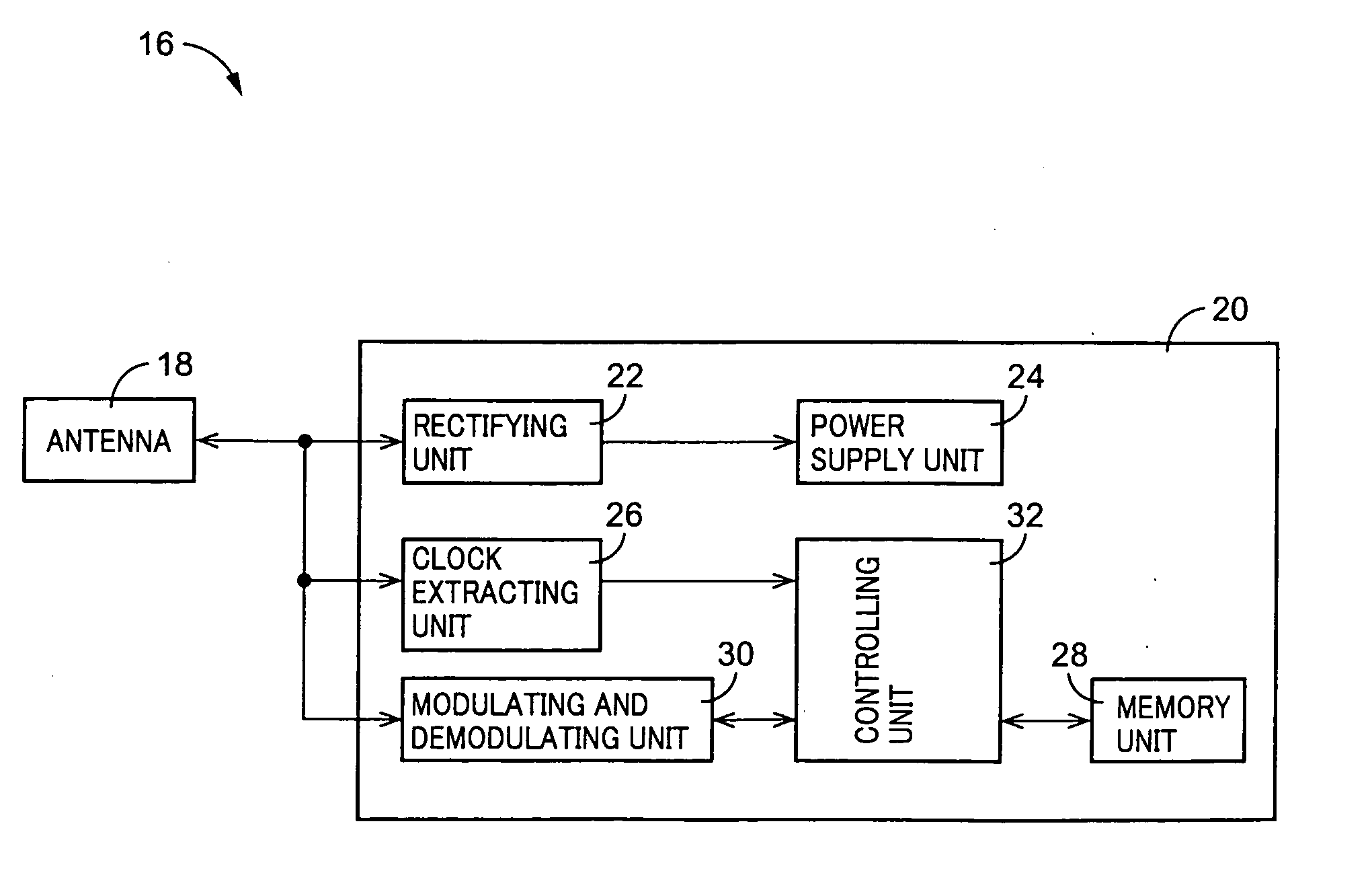
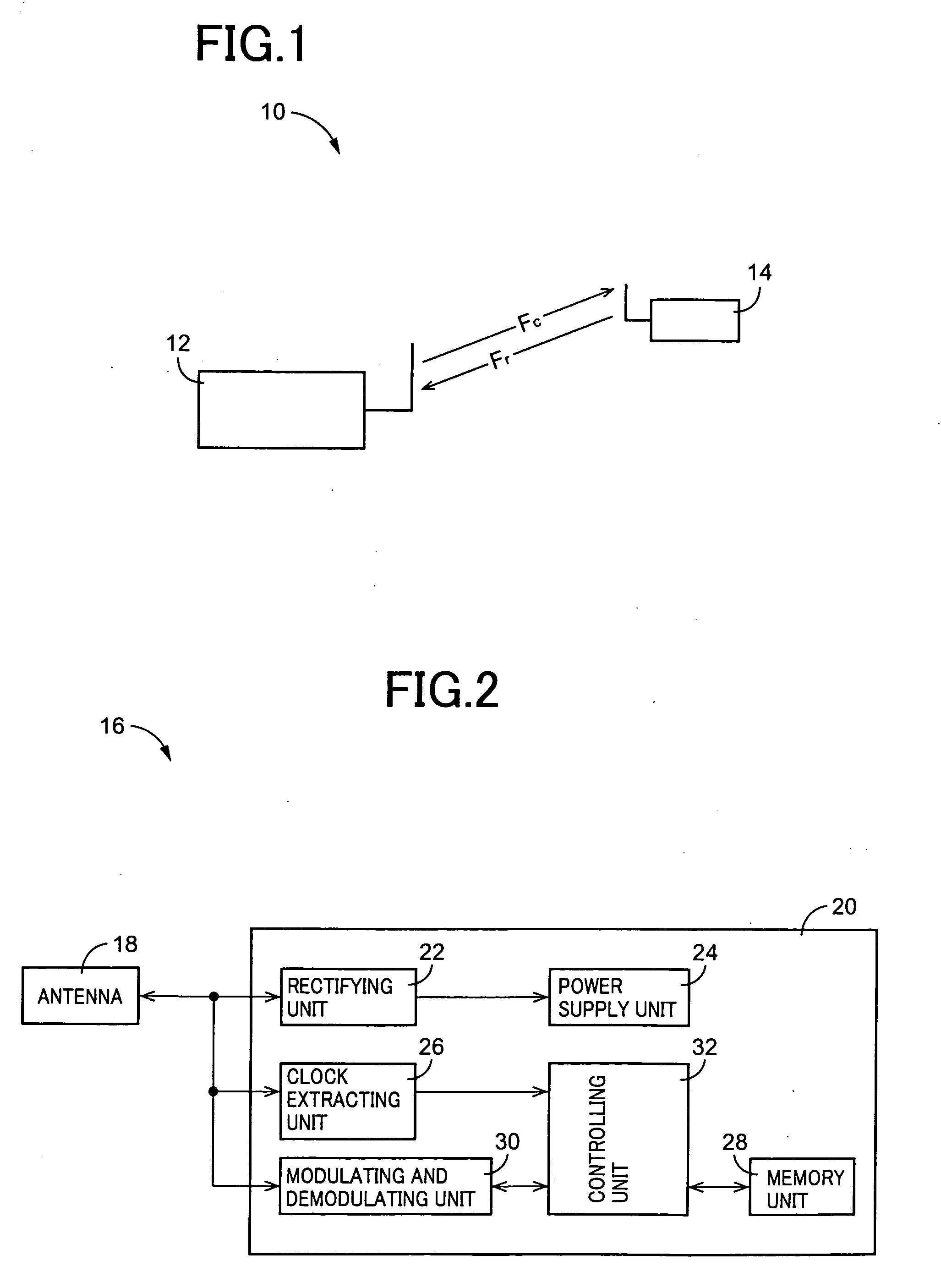
[0180]FIG. 1 is a diagram illustrating a radio-frequency i.e. wireless tag communication system 10 suitably using a radio-frequency communication device of a first invention. The radio-frequency tag communication system 10 is a so-called RFID (Radio Frequency Identification) system including a radio-frequency tag communication device 12 as one embodiment of the radio-frequency communication device of the first invention, and a singular or plurality of radio-frequency tags 14 (FIG. 1 shows a single tag) as a communication object for the radio-frequency tag communication device 12. The radio-frequency tag communication device 12 serves as an interrogator in the RFID system, and the radio-frequency tag 14 serves as a transponder in the system.

[0181]Specifically, the radio-frequency tag communication device 12 transmits an interrogating wave Fc (a transmitted signal) to the radio-frequency tag 14. The radio-frequency tag 14 receives the interrogating wave Fc to modulate it based on a pr...


PUM


Abstract

There is provided a radio-frequency communication device that can sufficiently eliminate a leakage signal from a transmission side included in a received signal. The communication device includes a cancel amplitude controlling unit 62 selectively suppressing supply of a cancel signal to a cancel signal synthesizing unit 52, a received-signal terminating unit 50 selectively terminating a received-signal input terminal 64i, a signal strength detecting unit 78 detecting a signal strength, a memory unit 82 storing a signal strength detected by the signal strength detecting unit 78, a signal strength comparing unit 80 comparing a plurality kinds of signal strengths read out from the memory unit 82, and a cancel signal controlling unit 72 controlling an amplitude and/or a phase of the cancel signal based on a result of the comparison by the signal strength comparing unit 80. Thus, suppressing the cancel signal by the cancel amplitude controlling unit 62 enables accurate detection of a strength of the received signal, as well as terminating the received signal by the received-signal terminating unit 50 enables accurate detection of a strength of the cancel signal.

Description

[0001]This application is based on Japanese Patent Application Nos. 2006-102031, 2006-135531, 2006-180160 and 2006-175936, the content of which are incorporated hereinto by reference.TECHNICAL FIELD[0002]The present invention relates to an improvement in a radio-frequency communication device that includes a cancellation circuit for suppressing a leakage signal from a transmission side.BACKGROUND ART[0003]There is known a radio-frequency communication device including a transmission section that transmits a predetermined transmitted signal via a transmission antenna and a reception section that receives, via a reception antenna, a reply signal returned in response to the transmitted signal. For example, there is illustrated a radio-frequency tag communication device (an interrogator) of an RFID (Radio-Frequency Identification) system that reads out information from a compact radio-frequency tag (a transponder) storing predetermined information, in a noncontacting manner. In the RFID...

Claims


Application Information

Patent Timeline
Patent Type & Authority Applications(United States)
IPC IPC(8): H04B15/00H04B17/00
CPCG01S7/038H04B7/0615H04B1/126G06K19/0723
Inventor NAGAI, TAKUYAOHASHI, TSUYOSHIHIRATA, HIRONORITAKEDA, MICHIHIROTAKI, KAZUNARI
Owner BROTHER KOGYO KK
Why Eureka
Try Eureka