Method for three-dimensional turbo spin echo imaging

a three-dimensional, echo imaging technology, applied in the field of magnetic resonance imaging, can solve problems such as reducing imaging efficiency, and achieve the effects of improving imaging efficiency, shortening imaging time, and improving imaging efficiency

Active Publication Date: 2011-11-03
SIEMENS HEALTHCARE GMBH
View PDF2 Cites 13 Cited by
  • Summary
  • Abstract
  • Description
  • Claims
  • Application Information

AI Technical Summary

Benefits of technology

An object of the present invention is to provide a method for three-dimensional turbo spin echo imaging that improves the imaging efficiency of a magnetic resonance imaging system.
It can be seen from the above-mentioned technical solution that the three-dimensional turbo spin echo imaging method provided by the present method includes applying a first slice selection gradient at the same time as applying each excitation pulse, and applying a second slice selection gradient at the same time as applying each refocusing pulse, so that the applied refocusing pulse each time only affects the current slab, and other slabs can be scanned simultaneously during the time period waiting for the excited protons in the current slab to return to the state before the excitation, therefore, the present invention shortens the imaging time and is able to improve imaging efficiency.
Based on the technology of an improved imaging efficiency, the present invention further provides a solution for image quality optimization. For example, slabs with odd serial numbers along the slice selection can be scanned first, then slabs with even serial numbers along the slice selection are scanned. Furthermore, the pulse frequency and the gradient polarity are adjusted respectively for fat-suppressed imaging and non-fat-suppressed imaging. The strength of the scan signals can be corrected by using histogram matching and three-dimensional interpolation after having acquired the scan signals, so that the image quality can be improved.

Problems solved by technology

Therefore, the imaging efficiency is reduced.

Method used


Image

  • Method for three-dimensional turbo spin echo imaging
  • Method for three-dimensional turbo spin echo imaging
  • Method for three-dimensional turbo spin echo imaging

Examples


first embodiment

The First Embodiment

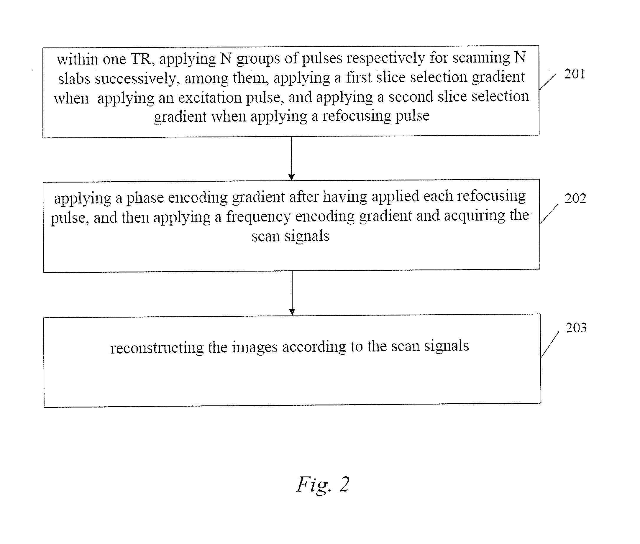
FIG. 2 is a flowchart of the first embodiment of a 3D-TSE imaging method provided by the present invention. As shown in FIG. 2, the method comprises the following steps:

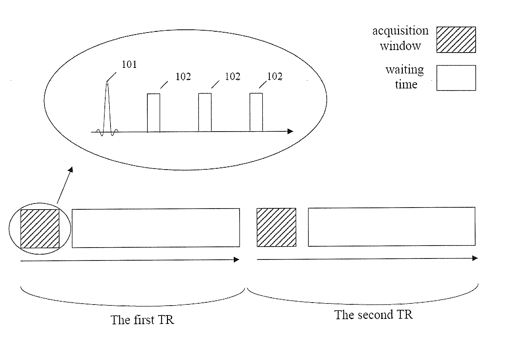
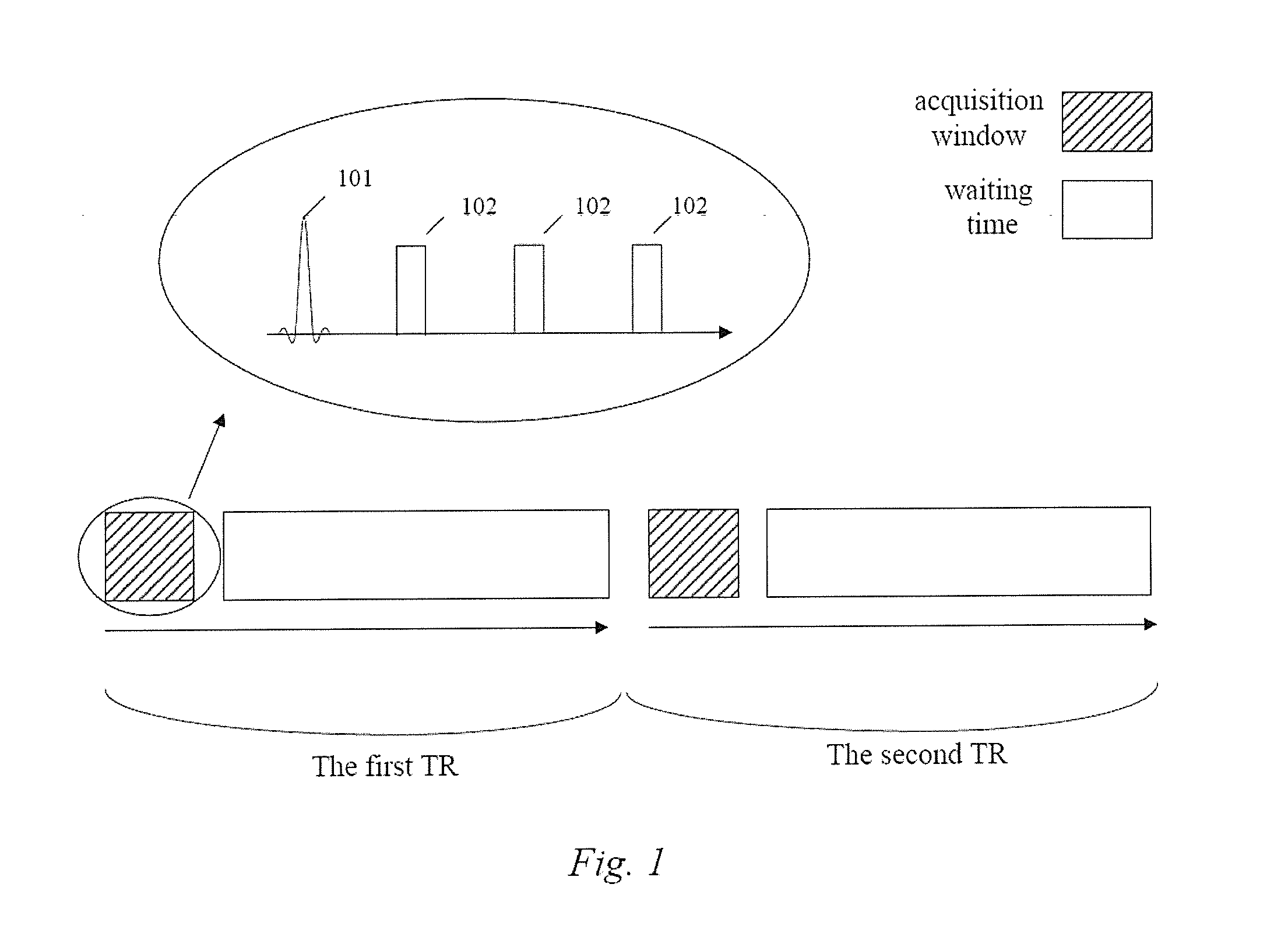
Step 201: within a TR, the magnetic resonance imaging system applies N groups of pulses for respectively scanning N slabs in succession, with each group including one excitation pulse and more than one refocusing pulse, and it applies a first slice selection gradient at the same time as applying each said excitation pulse, and applies a second slice selection gradient at the same time as applying each said refocusing pulse, wherein N is a positive integer greater than 1.

Step 202, the magnetic resonance imaging system applies a phase encoding gradient after having applied each refocusing pulse, then applies a frequency encoding gradient, and acquires the scan signals during the duration of the frequency encoding gradient.

Step 203, the magnetic resonance imaging system reconstructs images according ...

second embodiment

The Second Embodiment

The first embodiment achieves the object of improving imaging efficiency, but the image quality can be further optimized on the basis of the improvement of imaging efficiency, and the second embodiment will be described in detail below.

There are four points to be illustrated. First, as noted in the above description, a selective excitation pulse means applying excitation pulse and slice selection gradient to the examined tissues simultaneously, thus making the excitation pulse be selective, and a selective refocusing pulse means applying the refocusing pulse and slice selection gradient to the examined tissues simultaneously, thus making the refocusing pulse be selective. In the present invention the slice selection gradient matching the excitation pulse is designated as the first slice selection gradient, and the slice selection gradient matching the refocusing pulse is designated as the second slice selection gradient. It can be seen that in the same group of ...

third embodiment

The Third Embodiment

The second embodiment achieves the object of improving imaging efficiency and eliminating the sideband artifacts of the slab, but the image quality can be further optimized on the basis of the first embodiment and the second embodiment, and the third embodiment will be further described in detail below.

In practical applications, since the selectivity of excitation pulses or refocusing pulses is not ideal. Alternatively, since the inconsistency between the frequency of radio frequency pulses and the resonance frequency of the protons leads to the drift of the region of the excited protons compared with an ideal case, which finally reflects in the scan image and affects the strength and contrast of the scan signals to a certain extent. FIG. 7 is a schematic diagram of the strength and / or contrast of the scan signals. As shown in FIG. 7, the slab is divided into five regions by the straight lines L1, L2, L3, and L4 along the slice selection direction, in which the f...


PUM


Abstract

A three-dimensional turbo spin echo imaging method of applying, within a repetition time TR, N groups of pulses to respectively scan N slabs in succession, with each group including one excitation pulse and more than one refocusing pulse, wherein N is a positive integer greater than 1, is improved by applying a first slice selection gradient at the same time as applying each said excitation pulse, and applying a second slice selection gradient at the same time as applying each said refocusing pulse, and applying a phase encoding gradient after having applied each refocusing pulse, then applying a frequency encoding gradient and acquiring scan signals during the duration of the frequency encoding gradient. An image according to the scan signals is reconstructed.

Description

BACKGROUND OF THE INVENTION1. Field of the InventionThe present invention relates to the technical field of magnetic resonance imaging and, particularly, to a method for three-dimensional turbo spin echo imaging.2. Description of the Prior ArtThe principles of magnetic resonance imaging (MRI) are as follows. After having applied an external magnetic field, protons in the examined tissues are excited by radio frequency (RF) pulses and they absorb certain energy, which results in their resonance. When the radiation of RF pulses is stopped, the excited protons release the absorbed energy gradually in the form of scan signals. By then acquiring the scan signals and processing them using known image reconstruction technology, a scan image of the examined tissue can be obtained. In three-dimensional MRI imaging technology, slabs are used as units for the protons in the examined tissues to be excited, with each slab including several slices.In this case, the external magnetic field include...

Claims


Application Information

Patent Timeline
Patent Type & Authority Applications(United States)
IPC IPC(8): G01R33/48
CPCG01R33/4822G01R33/5617G01R33/4833
Inventor LI, GUO BINPAUL, DOMINIK
Owner SIEMENS HEALTHCARE GMBH
Why Eureka
Try Eureka