Multimode transceiver for use with multiple antennas and method for use therewith

a multi-mode transceiver and antenna technology, applied in the field of wireless communication, can solve the problems of antenna gain restriction, power restriction, modulation technique, and antenna gain, and cannot be implemented in the substantially two-dimensional space of an integrated circuit (ic)

Inactive Publication Date: 2009-05-21
BROADCOM CORP
View PDF13 Cites 34 Cited by
  • Summary
  • Abstract
  • Description
  • Claims
  • Application Information

AI Technical Summary

Problems solved by technology

While the ISM frequency spectrum is unlicensed there are restrictions on power, modulation techniques, and antenna gain.
An issue with such three-dimensional antennas is that they cannot be implemented in the substantially two-dimensional space of an integrated circuit (IC) and / or on the printed circuit board (PCB) supporting the IC.
As such, due to the antenna size, it cannot be implemented on-chip since a relatively complex IC having millions of transistors has a size of 2 to 20 millimeters by 2 to 20 millimeters.
While this advancement allows for reduction in size of electronic devices, it does present a design challenge of providing and receiving signals, data, clock signals, operational instructions, etc., to and from a plurality of ICs of the device.

Method used


Image

  • Multimode transceiver for use with multiple antennas and method for use therewith
  • Multimode transceiver for use with multiple antennas and method for use therewith
  • Multimode transceiver for use with multiple antennas and method for use therewith

Examples


Embodiment Construction

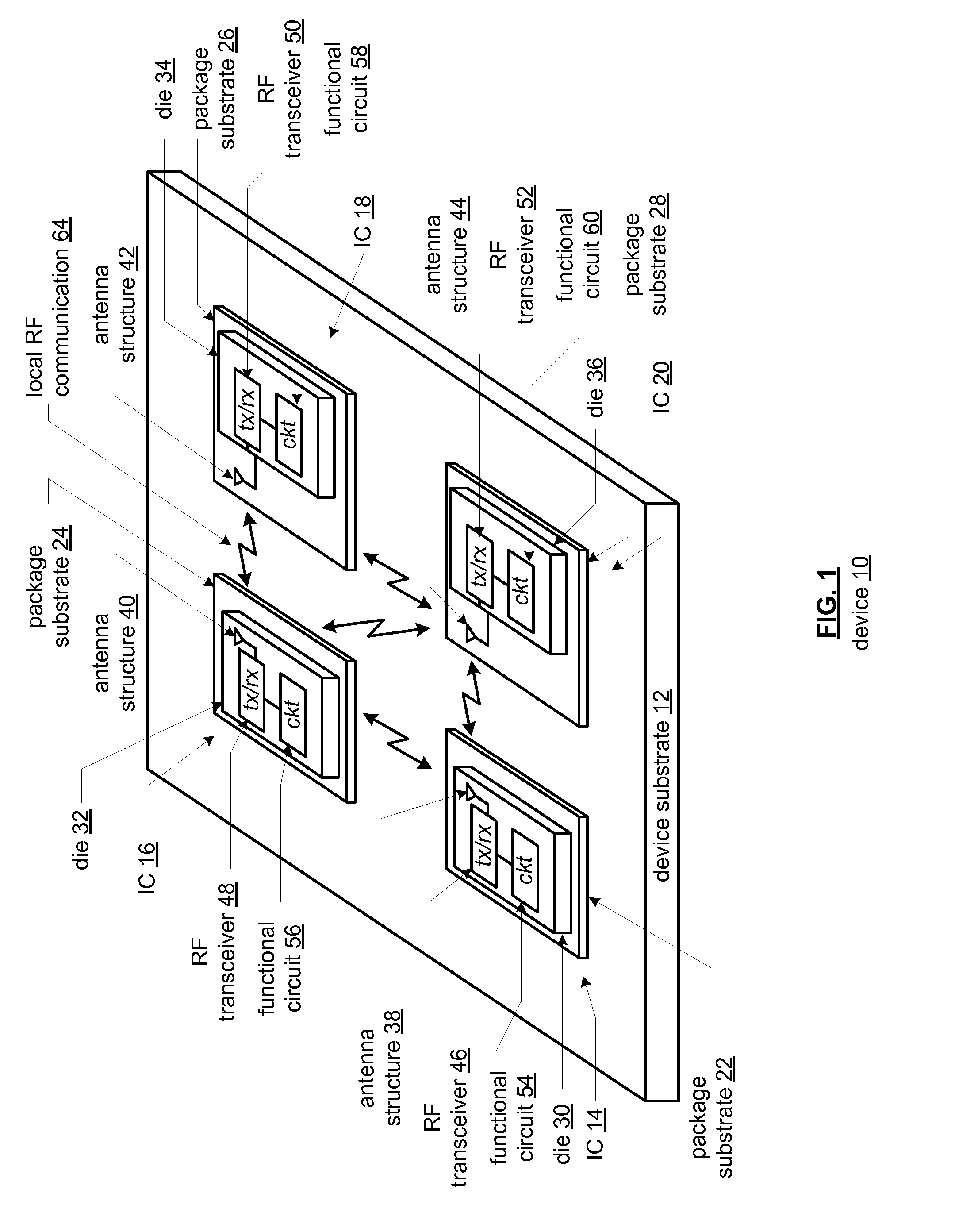
[0062]FIG. 1 is a diagram of an embodiment of a device 10 that includes a device substrate 12 and a plurality of integrated circuits (IC) 14-20. Each of the ICs 14-20 includes a package substrate 22-28 and a die 30-36. Dies 30 and 32 of ICs 14 and 16 include an antenna structure 38, 40, a radio frequency (RF) transceiver 46, 48, and a functional circuit 54, 56. Dies 34 and 36 of ICs 18 and 20 include an RF transceiver 50, 52 and a function circuit 58, 60. Package substrates 26 and 28 of ICs 18 and 20 include an antenna structure 42, 44 coupled to the RF transceiver 50, 52.

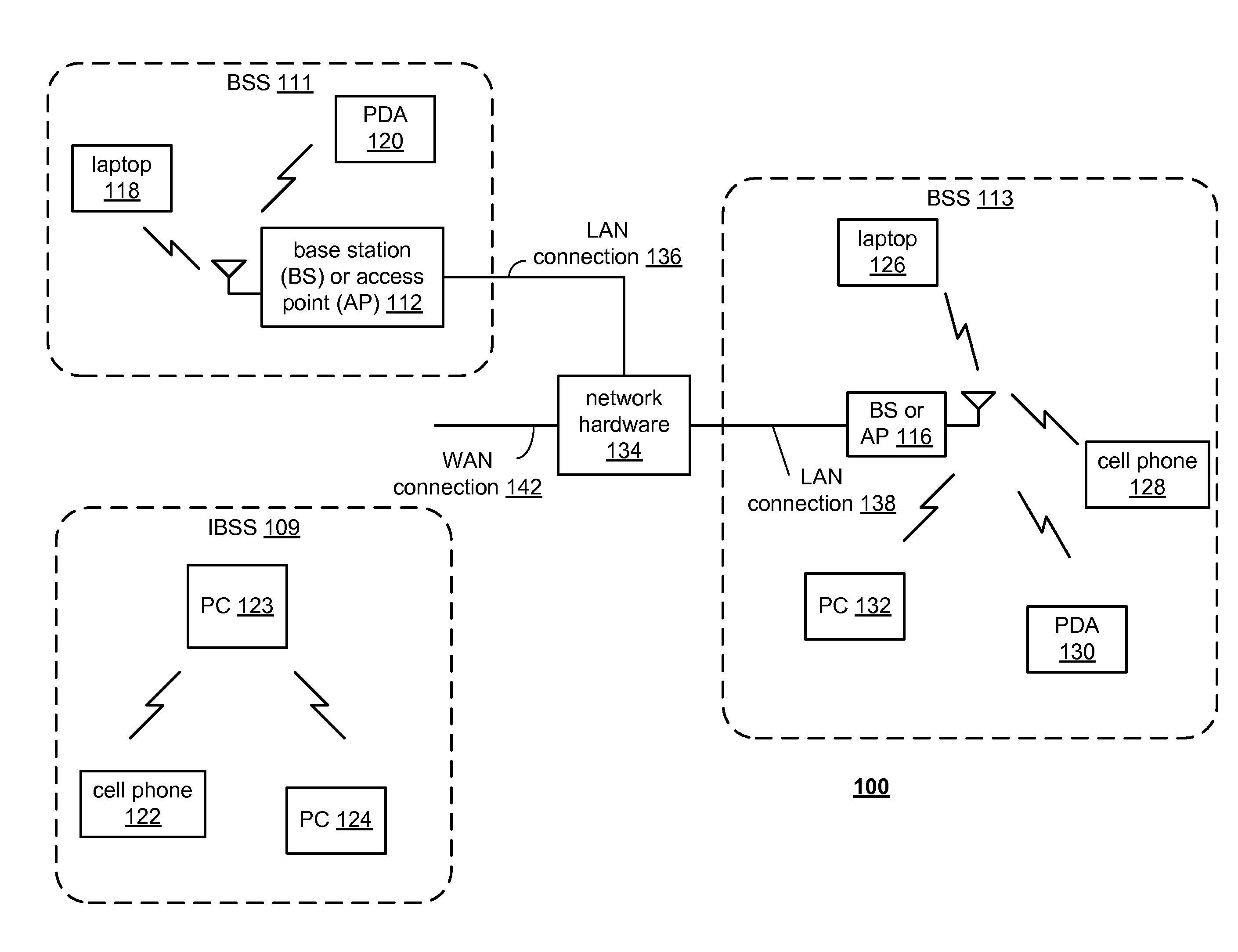
[0063]The device 10 may be any type of electronic equipment that includes integrated circuits. For example, but far from an exhaustive list, the device 10 may be a personal computer, a laptop computer, a hand held computer, a wireless local area network (WLAN) access point, a WLAN station, a cellular telephone, an audio entertainment device, a video entertainment device, a video game control and / or console, a radio...


PUM


Abstract

A wireless transceiver includes a plurality of antennas. A plurality of signal recovery circuits generate a selected number of received signals from a first subset of the plurality of antennas, based on a control signal. A receiver section recovers an inbound data stream from the selected number of received signals. A transmitter module generates a transmit signal to a selected one of the plurality of antennas, based on the control signal. The intersection between the first subset of the plurality of antennas and the selected one of the plurality of antennas is the null set for each value of the control signal. The control signals can be generated in multiple different operational modes including, for instance, a cyclic modes and a fixed mode of operation.

Description

CROSS REFERENCE TO RELATED PATENTS[0001]The present application claims priority under 35 U.S.C. 120 as a continuation-in-part of the copending application entitled, RECONFIGURABLE MIMO TRANSCEIVER AND METHOD FOR USE THEREWITH, having application Ser. No. 12 / 210,678, filed on Sep. 15, 2008, which is itself a continuation-in-part of the application entitled, AN INTEGRATED CIRCUIT ANTENNA STRUCTURE, having application Ser. No. 11 / 648,826, filed on Dec. 29, 2006, the contents of which are incorporated herein by reference thereto.[0002]In addition, the present application is related to TRANSCEIVER FOR USE WITH MULTIPLE ANTENNAS AND METHOD FOR USE THEREWITH having Ser. No. 12 / ______, filed on ______, the contents of which are incorporated herein by reference thereto.STATEMENT REGARDING FEDERALLY SPONSORED RESEARCH OR DEVELOPMENT[0003]NOT APPLICABLEINCORPORATION-BY-REFERENCE OF MATERIAL SUBMITTED ON A COMPACT DISC[0004]NOT APPLICABLEBACKGROUND OF THE INVENTION[0005]1. Technical Field of th...

Claims


Application Information

Patent Timeline
Patent Type & Authority Applications(United States)
IPC IPC(8): H04B1/38
CPCH01L23/66H01L25/0655H01L25/16H01L2223/6677H01L2924/19104H01L2924/3011H01Q1/2225H01L2924/0002H01Q1/2283H01Q1/38H01Q9/065H01Q23/00H01L2924/00
Inventor ROFOUGARAN AHMADREZA (REZA)
Owner BROADCOM CORP
Why Eureka
Try Eureka