
Method for Incremental, Timing-Driven, Physical-Synthesis Using Discrete Optimization

Active Publication Date: 2009-05-21
SIEMENS PROD LIFECYCLE MANAGEMENT SOFTWARE INC
View PDF3 Cites 8 Cited by
  • Summary
  • Abstract
  • Description
  • Claims
  • Application Information

AI Technical Summary

Benefits of technology

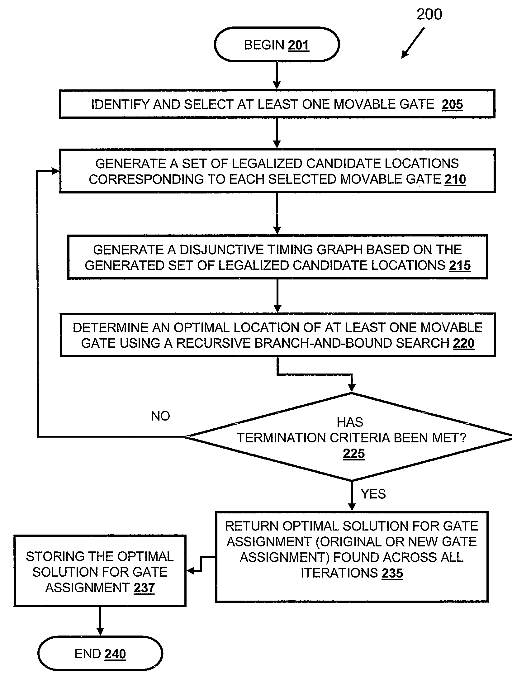
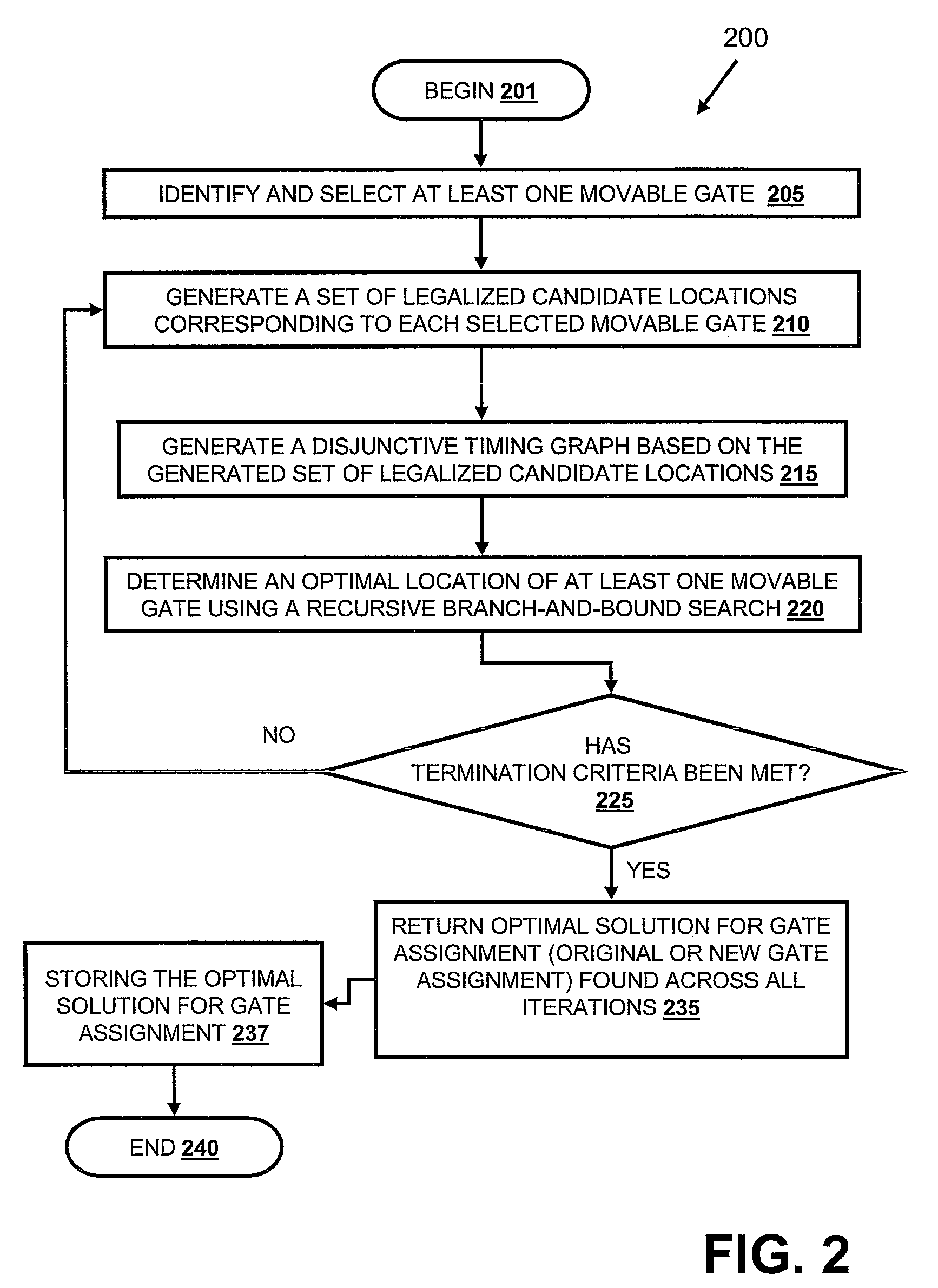
[0007]Disclosed are a method, system, and computer program product for optimizing a timing-driven placement of one or more movable gates of a circuit in a physical synthesis flow using a non-linear delay model. A path smoothing utility is provided, which executes on a processing device/computer to: (a) identify one or more movable gates based on at least one selection criteria; (b) generate a set of legalized candidate locations corresponding to one or more identified movable gates; (c) generate a disjunctive timing graph based on the gener

Problems solved by technology

While several solutions to this problem exist, there are several drawbacks to these existing solutions.
One major drawback of existing solutions is that these existing solutions consider only the placement of a single, movable gate within an integrated circuit design.
In addition, existing physical synthesis optimization methods consider gates (i.e., clocked repeaters and unclocked repeaters, such as buffers and inverters) that are adjacent to a single, movable gate as unmovable.
This designation of certain gates as unmovable can possibly over constrain gate placement optimization efforts.
However, in later stages of refinement when re-buffering is not permitted, the linear delay model does not hold.
Moreover, the presence of obstacles and keep-out regions on the chip circuit often limits the possible legal locations for a particular gate.
When there are obstacles to gate placement, feasible candidate positions may need to be discretized, a task that cannot be performed by the LP formulation within RUMBLE.
Thus, an exhaustive enumeration approach would fare poorly in large problem instances, as the number of possible gate assignments grows exponentially with the number of movable gates (i.e., with M movable gates and C candidates per gate, a total of MC gate assignments would be generated).

Method used


Image

  • Method for Incremental, Timing-Driven, Physical-Synthesis Using Discrete Optimization
  • Method for Incremental, Timing-Driven, Physical-Synthesis Using Discrete Optimization
  • Method for Incremental, Timing-Driven, Physical-Synthesis Using Discrete Optimization

Examples


Embodiment Construction

[0007]Disclosed are a method, system, and computer program product for optimizing a timing-driven placement of one or more movable gates of a circuit in a physical synthesis flow using a non-linear delay model. A path smoothing utility is provided, which executes on a processing device / computer to: (a) identify one or more movable gates based on at least one selection criteria; (b) generate a set of legalized candidate locations corresponding to one or more identified movable gates; (c) generate a disjunctive timing graph based on the generated set of legalized candidate locations; (d) determine an optimal location of one or more movable gate(s) using a recursive branch-and-bound search; and (e) store the optimal location in the processing device / computer. According to one embodiment, in addition to gate placement, the disjunctive timing graph permits additional discrete transforms that are associated with a plurality of optimization variables. Such optimization variables include, b...


PUM


Abstract

A method, data processing system and computer program product for optimizing the placement of logic gates of a subcircuit in a physical synthesis flow. A Path Smoothing utility identifies one or more movable gates based on at least one selection criteria. A set of legalized candidate locations corresponding to one or more identified movable gates is generated. A disjunctive timing graph based on the generated set of legalized candidate locations is then generated. An optimal location of one or more movable gate(s) is determined using a recursive branch-and-bound search and stored in the computing device.

Description

BACKGROUND OF THE INVENTION[0001]1. Technical Field[0002]The present invention generally relates to integrated circuit design tools and in particular to integrated circuit design tools that optimize area, performance, and signal integrity in integrated circuits.[0003]2. Description of the Related Art[0004]Existing methods have sought to improve the placement of negative-slack gates of a circuit in a physical synthesis flow. While several solutions to this problem exist, there are several drawbacks to these existing solutions. One major drawback of existing solutions is that these existing solutions consider only the placement of a single, movable gate within an integrated circuit design. In addition, existing physical synthesis optimization methods consider gates (i.e., clocked repeaters and unclocked repeaters, such as buffers and inverters) that are adjacent to a single, movable gate as unmovable. This designation of certain gates as unmovable can possibly over constrain gate plac...

Claims


Application Information

Patent Timeline
IPC IPC(8): G06F17/50
CPCG06F2217/84G06F17/5072G06F30/392G06F2119/12
Inventor ALPERT, CHARLES J.LI, ZHUOMOFFITT, MICHAEL D.PAPA, DAVID A.
Owner SIEMENS PROD LIFECYCLE MANAGEMENT SOFTWARE INC
Learn More