

Photosensitive Material Conveying System and Image Forming Apparatus
- Summary
- Abstract
- Description
- Claims
- Application Information
AI Technical Summary
Benefits of technology
Problems solved by technology
Method used
Image

Examples
example of implementation
[0069]To begin with, the photosensitive film was prepared in the following manner. That is, the photosensitive film was prepared in a manner similar to that of the sample number 115 in the Implementation Example 1 described in lines [0480] to [0519] of the of the Unexamined Japanese Patent Application Publication No. 2005-107496 applied for by the present applicants. However, the matting agent “3-dimensionally cross-linked polymethyl methacrylate: PMMA, average particle diameter 10 μm, truly spherical shape, degree of monodispersion 10%” was employed in place of the matting agent (3-dimensionally cross-linked polymethyl methacrylate: PMMA, average particle diameter 5 μm) in the “BC layer protective layer coating liquid” described in line [0494].
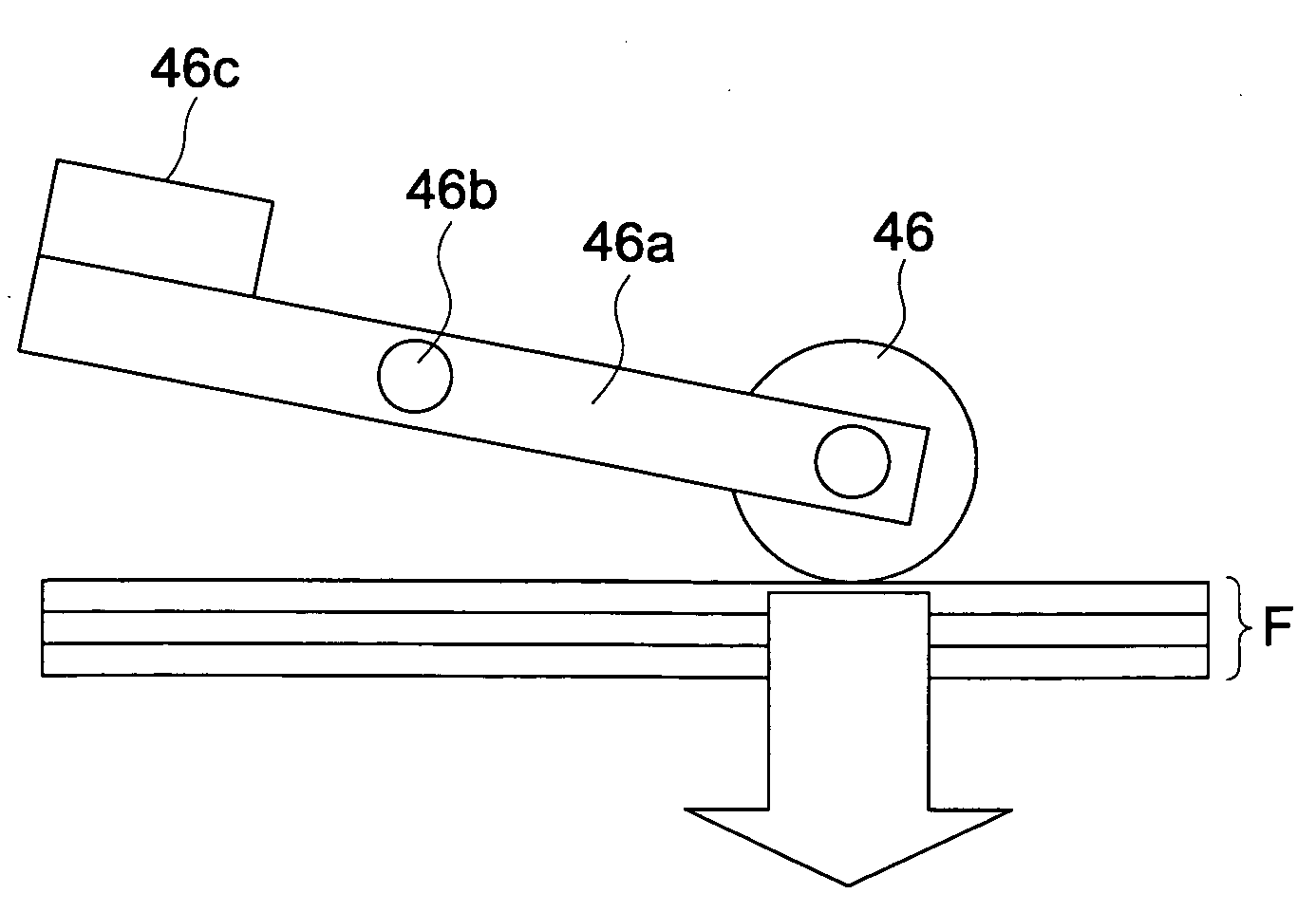
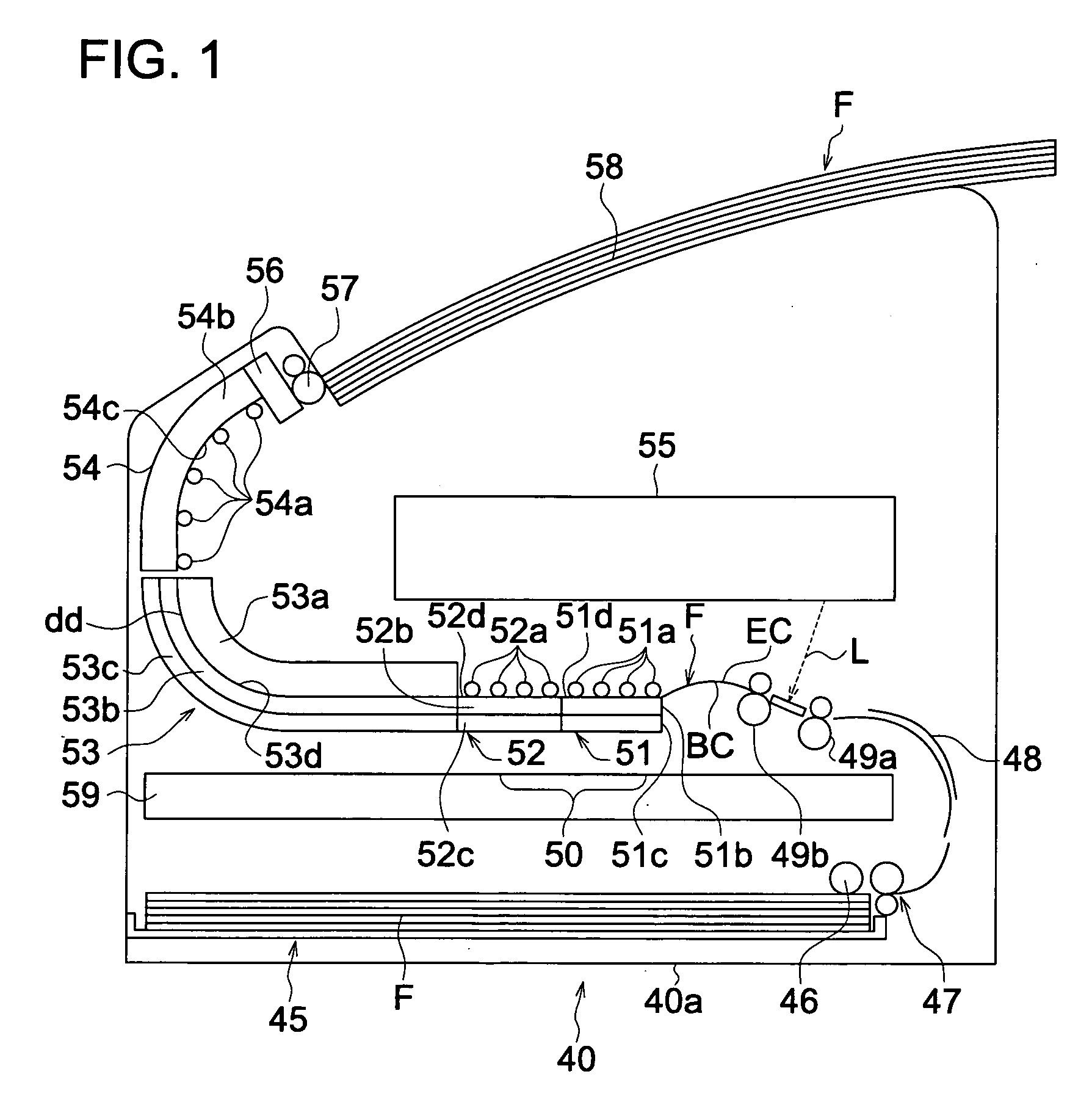
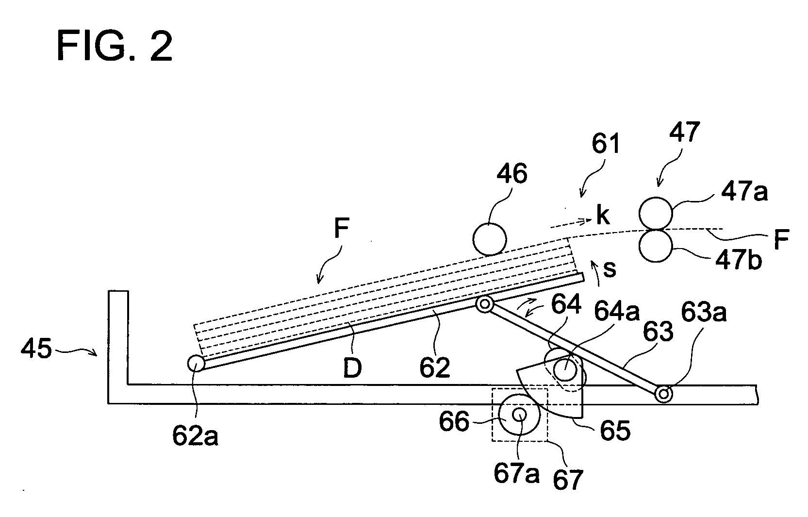
[0070]After feeding out films using the above film as shown in FIG. 1 to FIG. 4, a solid image with a density 2 was formed, developed, and the transmission image scratches were visually measured using a high luminosity X-ray film viewer. The ...
PUM
 Abstract
Description
Claims
Application Information