Optical recording medium, optical recording apparatus, optical recording method, and optical reproducing method

Inactive Publication Date: 2009-05-28
FUJIFILM CORP
View PDF6 Cites 9 Cited by
  • Summary
  • Abstract
  • Description
  • Claims
  • Application Information

AI Technical Summary

Benefits of technology

[0030]In the optical recording medium according to the item <15>, two or more cholesteric liquid crystal layers are formed in a laminate structure, and when the incidence angle is varied, displacement of the selective reflection wavelength arises. Therefore, noise caused by such diffused light is not overlapped on a reproduced image then to be detected by a CMOS sensor or on CCD, and a reproduced image can be detected at least to such an extent that errors can be corrected. The greater amount of a noise component by diffused light requires greater multiplicity of the hologram. That is, the greater the multiplicity is, the smaller the diffraction efficiency is, e.g., when the multiplicity is 10 or more, a diffraction efficiency from one hologram is extremely small. When diffused noise is caused, it is extremely difficult to detect a reproduced image. The present invention makes it possible to eliminate difficulties and can realize the high density image recording which has not been achieved conventionally.

Problems solved by technology

However, all of the conventionally proposed optical recording media are based on two dimensional recording, and increasing of recording capacity has been limited.
However, such a transmission optical recording medium 20 requires forming the reflective film 2 and the first gap layer 8 between the second substrate 1 and the recording layer 4, which causes problems with an increase in thickness of the optical recording medium and a complicated layer structure.
Therefore, the optical recording medium has problems that recording and reproducing of the optical recording medium depends on the mechanical accuracy of the optical reproducing apparatus used, there is a limitation in the accuracy of recording and reproducing, and it is difficult to even-out variations in recording position of the optical recording medium and dimension error of the optical recording medium itself.

Method used


Image

  • Optical recording medium, optical recording apparatus, optical recording method, and optical reproducing method
  • Optical recording medium, optical recording apparatus, optical recording method, and optical reproducing method
  • Optical recording medium, optical recording apparatus, optical recording method, and optical reproducing method

Examples


example 1

Preparation of Optical Recording Medium

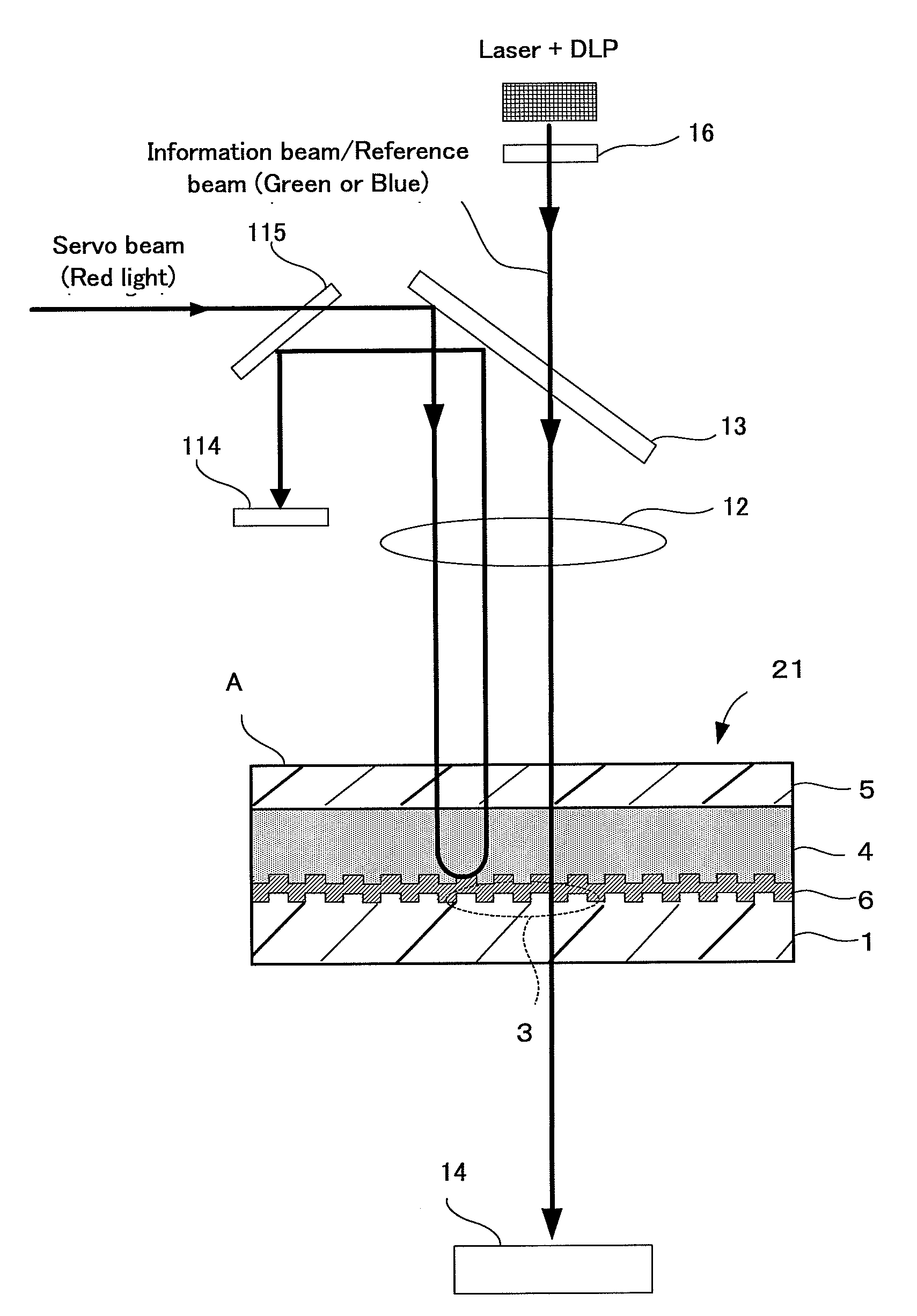
[0241]An optical recording medium of Example 1 was prepared as follows such that a first substrate, a recording layer, a filter layer and a second substrate were formed in this order in a laminate structure. The filter layer was formed and laminated on the second substrate by sputtering according to the following forming method of a dielectric deposition filter.

Simulation of Film-Thickness Structure of Dielectric Deposition Layer and Reflection Characteristics Thereof—

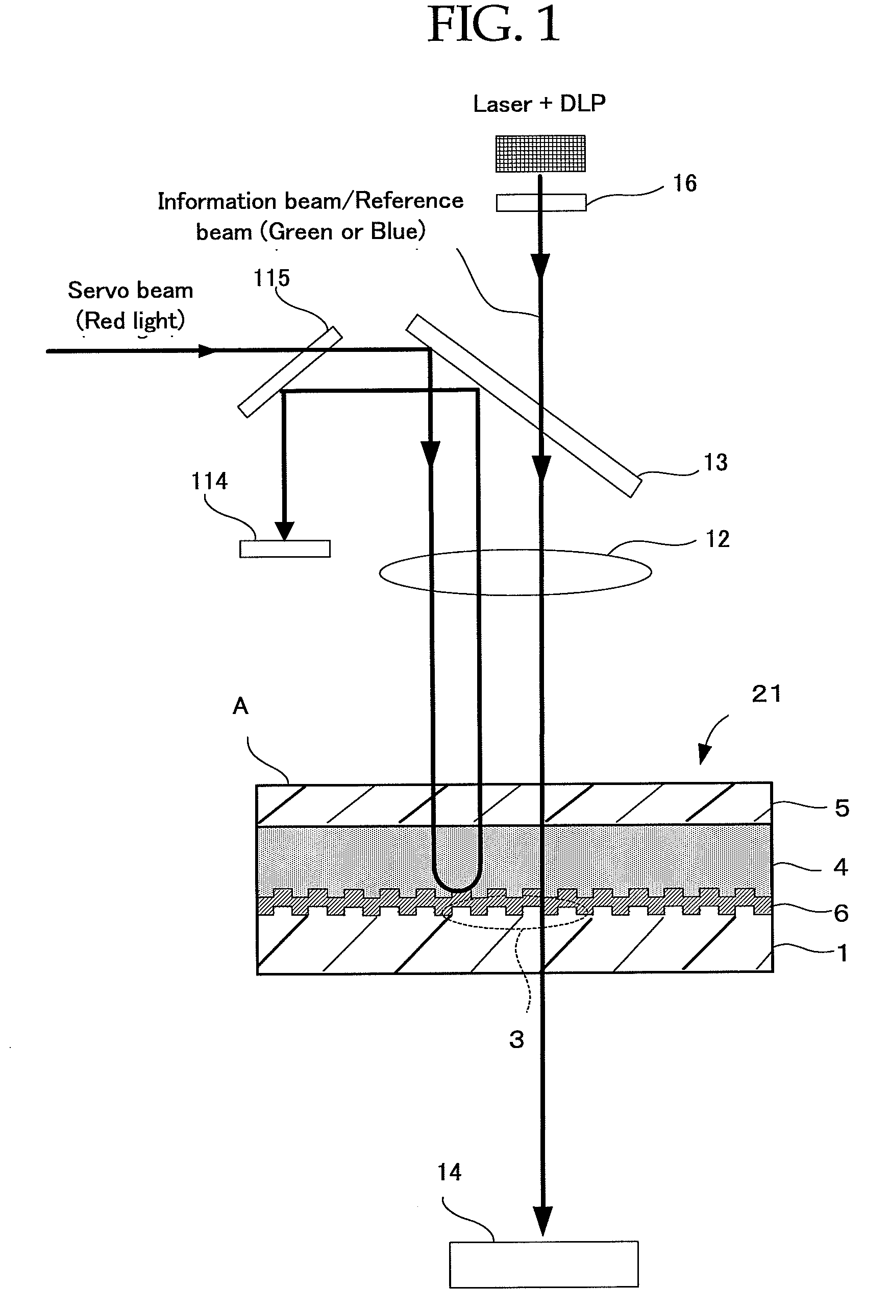
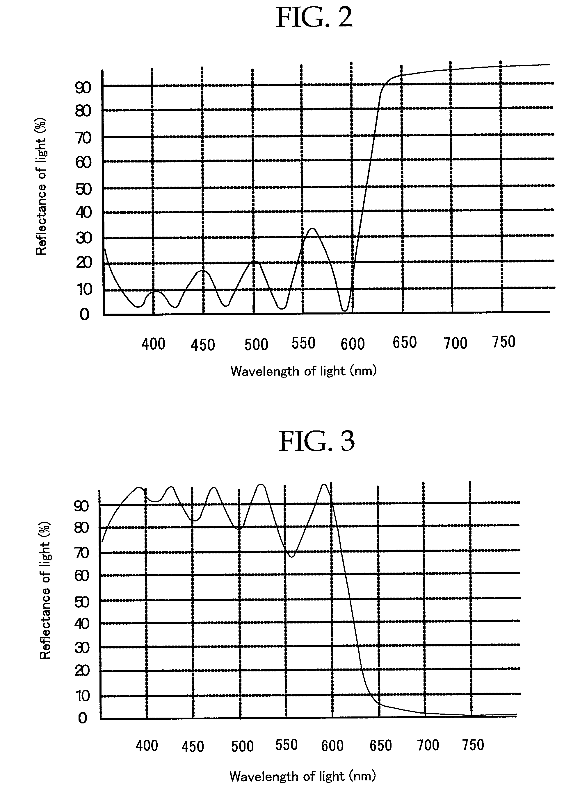
[0242]Subsequently, the film-thickness structure and reflection characteristics of a dielectric deposition layer using optical thin-film calculation software (brand name: TFCalc, manufactured by Software Spectra Co.) under the following calculation conditions.

[0243]For refractive indexes of TiO2 and SiO2, data base values based on TFCalc were used.

[0244]The thickness was optimized so that the reflectance at a wavelength of 650 nm and the transmittance at a wavelength of 532 nm we...


PUM


Abstract

The present invention aims to provide an optical recording medium that is provided with a recording layer for recording information by holography, has an uncomplicated laminate structure, is capable of performing recording and reproducing control such as tracking control and is capable of high-density multiple recording, as well as an optical recording method, an optical recording apparatus and an optical reproducing method. To this end, the present invention provides an optical recording medium which is a transmission medium for recording information based on a holographic principle using an information beam and a reference beam and performing tracking control using a servo beam, the medium including at least a first substrate, a recording layer, a filter layer that selectively reflects the servo beam, and a second substrate being disposed in this order as viewed from the light irradiation side of the information beam and the reference beam.

Description

TECHNICAL FIELD[0001]The present invention relates to a transmission optical recording medium that is provided with a recording layer for recording information by holography, is capable of performing recording and reproducing control such as tracking control and has an uncomplicated laminate structure, and also relates to an optical recording apparatus, an optical recording method and an optical reproducing method.BACKGROUND ART[0002]An optical recording medium is exemplified as one of recording media in which information in large volume such as high-density image data can be written. As this type of optical recording medium, for example, rewritable optical recording media such as optical magnetic discs and phase change optical discs, and write-once type optical recording media such as CD-R have been put in practical use, however, requests for further enlarging the capacity of the optical recording media are going on increasing. However, all of the conventionally proposed optical re...

Claims


Application Information

Patent Timeline
IPC IPC(8): G11B7/00G11B7/24G11B7/24044G11B7/2405G11B7/24062
CPCG11B7/245G11B7/246G11B7/252G11B7/256G03H1/0252G11B7/24044G03H2250/34G11B7/0065G11B7/00781G11B7/24038G03H2001/2234
Inventor USAMI, YOSHIHISAYUMOTO, MASATOSHIYANAGIHARA, NAOTO
Owner FUJIFILM CORP
Why Eureka
Try Eureka