Audio level compressor

a compressor and audio technology, applied in the field of audio signal processing, can solve the problems of accidental overload, high level of audio signal, temperature rise in filament, etc., and achieve the effect of convenient connection, improved harmony, and more reliability

Inactive Publication Date: 2009-05-28
OSBORNE GARY T
View PDF28 Cites 12 Cited by
  • Summary
  • Abstract
  • Description
  • Claims
  • Application Information

AI Technical Summary

Benefits of technology

[0017]Embodiments can also provide an in-line audio level compressor having a body with an input end and an output end, and an audio compression circuit means for compressing the dynamic range of an audio signal from an audio signal source. A means for receiving the input audio signal is located at the input end. A means for providing a compressed output audio signal from the in-line audio level compressor is located at the output end. The means for receiving the input audio signal can include a 3-pin female XLR connector. The means for providing a compressed output audio signal can include a 3-pin male XLR connector. To provide power to the compression circuit means, the in-line audio compressor can have a power conditioning circuit means for receiving phantom power from a phantom power source located outside the microphone, and conditioning the power for the compression circuit means, where the power conditioning circuit means receives the phantom power through the means for providing a compressed output audio signal from the in-line audio level compressor. The in-line compressor can be easily connected between an audio signal source and a mixing console to provide audio level compression for a musical instrument, an audio microphone not having a “built-in” compressor, or another audio signal source.
[0018]Some embodiments do not need to have a battery. Instead, power can be received from a phantom power source through a 3-pin male XLR output connector that also sends the audio signal to the mixing console. Operating without a battery can provide an advantage because the in-line compressor can be smaller, more reliable, and in better harmony with the time-constrained, demanding environment of live performance preparation.

Problems solved by technology

The rate of power dissipation and other factors create a temperature rise in the filament.
Accidental overload occurs when the audio signal reaches an extreme, unexpected high level.
Accidental overload can damage the power amplifier, loudspeaker, and the ear drums of nearby listeners.
When the audio program is produced by a microphone, accidental overload can be a common occurrence and a nuisance.
Even though a variety of prior-art professional quality compressors are commercially available, they are sometimes not used with stage microphones because the setup time is prohibitive.
By live-sound testing, it was discovered that the time constraints and demands of preparing a live performance caused band members (musicians and vocalists) to have little interest in using compressors for microphones.
Given the choice, the band members did not want to use the microphone without the compressor because it was so inferior in their opinions.

Method used


Image

  • Audio level compressor
  • Audio level compressor
  • Audio level compressor

Examples


Embodiment Construction

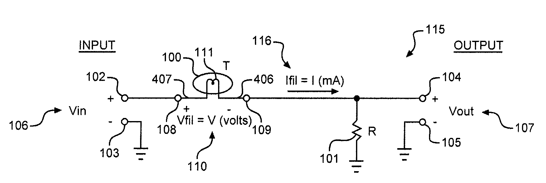
[0062]FIG. 1 shows a compressor 115 comprising an incandescent lamp 100; a load resistor 101; a pair of input terminals 102, 103; and a pair of output terminals 104, 105. The lamp 100 has a filament resistance of T ohms, and the resistor 101 has a constant resistance of R ohms. In operation, an input audio signal 106 having and RMS value of Vin volts is applied to the input terminals 102, 103, and an output audio signal 107 having and RMS value of Vout volts is produced at the output terminals 104, 105.

[0063]The lamp 100 and the resistor 101 create a voltage divider where the input signal 106 (Vin) is divided between a filament voltage 110 (Vfil) and the output signal 107 (Vout). The filament voltage 110 is measured at lamp terminals 108, 109 and has a RMS value of Vfil volts, where:

Vfil=VinTR+T(1)

The output signal Vout measured at terminals 104, 105 is:

Vout=VinRR+T(2)

Equation 2 can be rearranged to give a transfer function

VoutVin=RR+T(3)

which determines the signal gain of the compr...


PUM


Abstract

An audio level compressor for compressing the dynamic range of an input audio signal. The audio level compressor can be part of a microphone, or a separate component. The audio level compressor includes input terminals for receiving the input audio signal, a lamp having a filament resistance that is a function of the input audio signal; a load resistance; a signal gain controller that includes a means for increasing dynamic range compression of the input audio signal, and output terminals for providing an output audio signal that is a function of the input audio signal and the signal gain. The signal gain controller provides a signal gain that is a function of the filament resistance and the load resistance. The audio level compressor can also include an expander circuit or a power conditioning circuit. Power can be provided by an internal source or a phantom power supply.

Description

[0001]This application claims priority to U.S. Provisional Patent Application No. 60 / 988,540, filed Nov. 16, 2007, entitled “Audio Level Compressor.”BACKGROUND AND SUMMARY[0002]This invention relates to audio signal processing, and more specifically to a novel combination of an incandescent lamp and an audio amplifier for compressing the dynamic range of an audio signal carrying an audio program. Dynamic range compression is the action of automatically increasing the volume of quiet portions of the audio program and decreasing the volume of loud portions of the audio program.[0003]In embodiments of the invention, an amplifier amplifies an audio signal and applies a voltage to a lamp's filament. The applied voltage causes a current to flow through the filament which dissipates power at a rate determined by the product of the applied voltage times the induced current. The rate of power dissipation and other factors create a temperature rise in the filament. A given increase in the aud...

Claims


Application Information

Patent Timeline
Patent Type & Authority Applications(United States)
IPC IPC(8): H03G3/00
CPCH03G7/004H03G7/001
Inventor OSBORNE, GARY T.
Owner OSBORNE GARY T
Why Eureka
Try Eureka