Non-Linear Signal Distortion Detection Using Multiple Signal to Noise Ratio Measurement Sources

a signal distortion and noise ratio technology, applied in the field of television signal processing devices, can solve the problems of undecodable level of signal corruption and lower desired channel power downstream, and achieve the effect of optimizing tuning and optimizing tuning

Inactive Publication Date: 2009-05-28
MAGNOLIA LICENSING LLC
View PDF8 Cites 23 Cited by
  • Summary
  • Abstract
  • Description
  • Claims
  • Application Information

AI Technical Summary

Benefits of technology

[0004]In accordance with an aspect of the present invention, an apparatus for tuning an RF signal is disclosed. According to an exemplary embodiment, the apparatus is presented for utilizing information generated during digital signal processing operations to optimize the tuning and RF and IF signal conditioning operations. More specifically, said apparatus comprises a first processor for generating a first automatic gain control signal in response to a non-linear distortion figure of said RF signal.
[0005]In accordance with another aspect of the invention, a method of tuning an RF signal is disclosed. According to an exemplary embodiment, the method utilizes information generated during digital signal processing operations to optimize the tuning and RF and IF signal conditioning operation. More specifically, the method comprises the steps of receiving an RF signal, amplifying said RF signal responsive to a first automatic gain control signal, demodulating said RF signal, estimating a non-linear distortion figure of said RF signal, and adjusting said first automatic control signal in response to said non-linear distortion figure.

Problems solved by technology

Those skilled in the art will recognize the need to amplify the signal prior to the SAW filter, as the latter will normally have a significant insertion loss, or attenuation, as a result.
If there is a strong undesired signal present, the total power seen by the analog detector will also be higher and the detector output will drive the RF gain down, resulting in a lower desired channel power downstream.
In an analog television signal processing apparatus, some non-linear distortion was acceptable, whereas in a digital system, non-linear distortion can result in a level of signal corruption that is undecodable.

Method used


Image

  • Non-Linear Signal Distortion Detection Using Multiple Signal to Noise Ratio Measurement Sources
  • Non-Linear Signal Distortion Detection Using Multiple Signal to Noise Ratio Measurement Sources
  • Non-Linear Signal Distortion Detection Using Multiple Signal to Noise Ratio Measurement Sources

Examples


Embodiment Construction

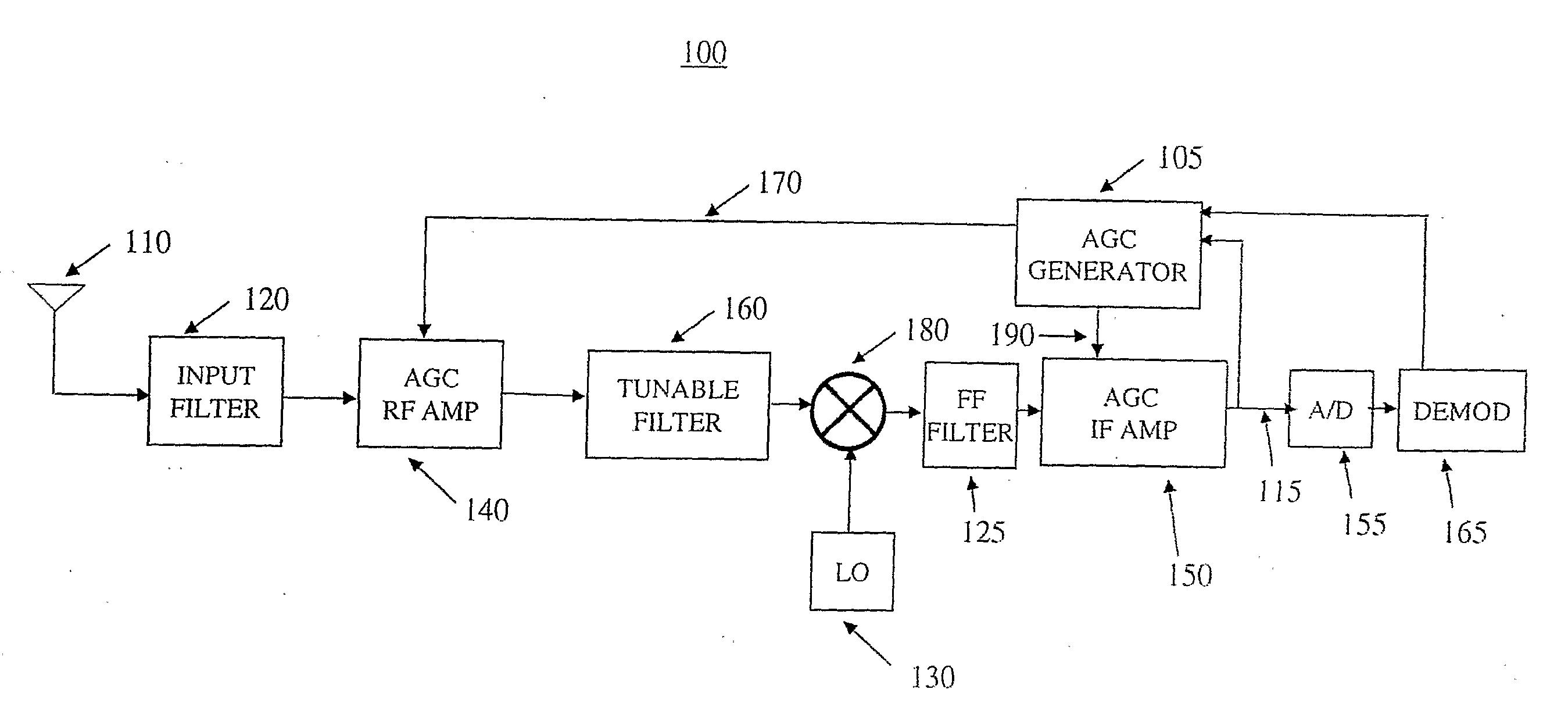
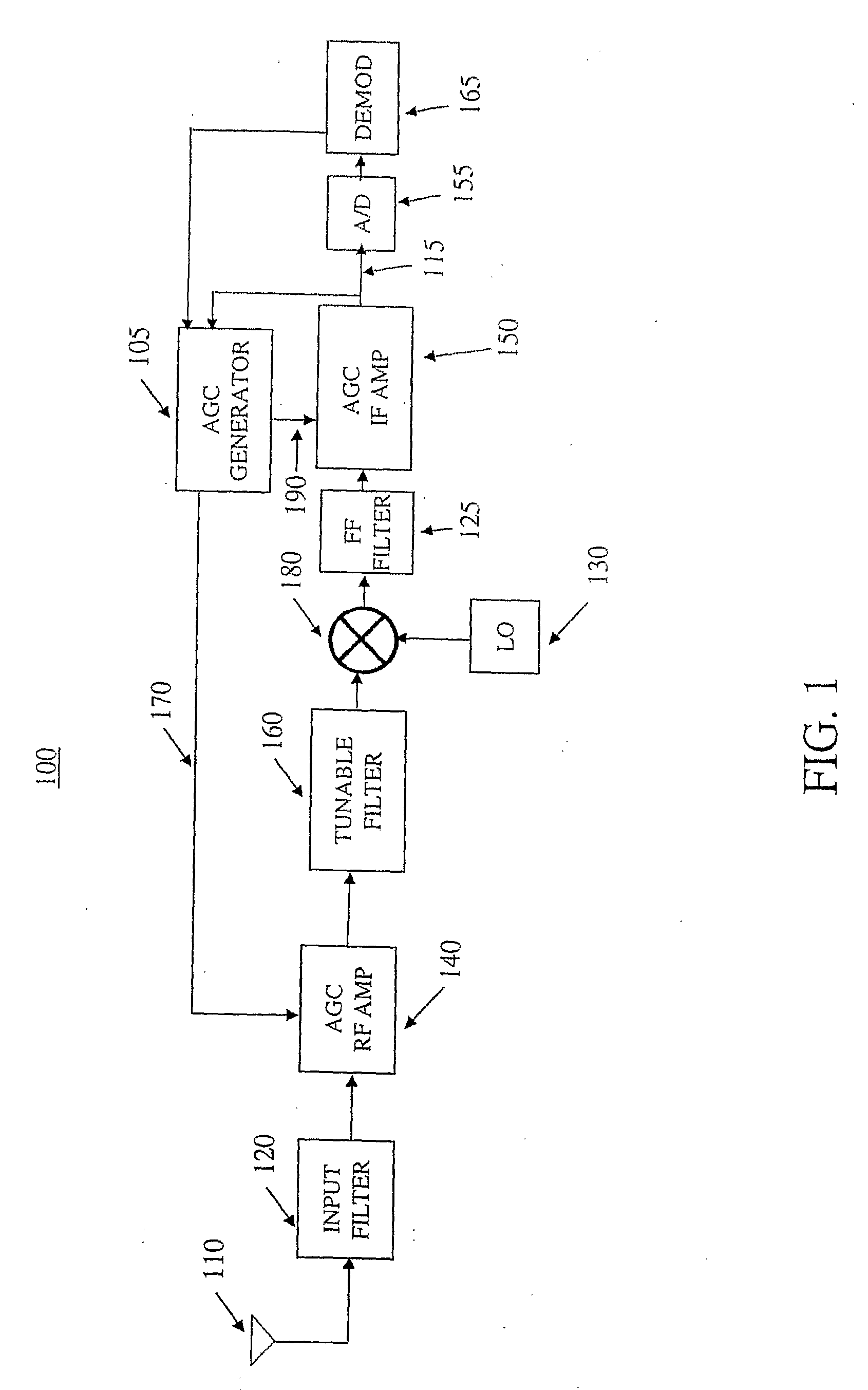
[0012]The exemplifications set out herein illustrate preferred embodiments of the invention, and such exemplifications are not to be construed as limiting the scope of the invention in any manner. Other than the inventive concept, the elements shown in the figures are well known and will not be described in detail. Also, familiarity with television broadcasting and receivers is assumed and is not described in detail herein. For example, other than the inventive concept, familiarity with current and proposed recommendations for TV standards such as NTSC (National Television Systems Committee), PAL (Phase Alternation Lines), SECAM (SEquential Couleur Avec Memoire) and ATSC (Advanced Television Systems Committee) (ATSC) is assumed. Likewise, other than the inventive concept, transmission concepts such as eight-level vestigial sideband (8-VSB), Quadrature Amplitude Modulation (QAM), and receiver components such as a radio-frequency (RF) front-end, or receiver section, such as a low nois...


PUM


Abstract

A television signal processing apparatus comprising a receiver comprises a distortion estimator and an automatic gain control signal generator. The automatic gain control signal generator generates a plurality of automatic gain control and filter response control signals in response to the magnitude or signal to noise ratio of an RF signal and a non-linear distortion figure generated from the information carried by said RF signal. The distortion estimator uses a plurality of statistical methods to generate a non-linear distortion figure from the signal constellation of the information carried by said RF signal.

Description

CROSS REFERENCE TO RELATED APPLICATION[0001]This application claims priority to and all benefits accruing from a provisional application filed in the United States Patent and Trademark Office on Mar. 24, 2005, and there assigned Ser. No. 60 / 664,917.BACKGROUND OF THE INVENTION[0002]In a processing device of television signals it is necessary to process the radio frequency (RF) received signal before the signal is converted to a digital representation by the analog to digital converter (ADC). Such circuitry generally includes one or more amplifiers and one or more filters. Generally, a first RF gain amplifier is followed by a first out of band rejection filter, followed by a mixer for converting the signal to an intermediate frequency (IF), followed by a fixed frequency filter, such as a surface acoustic wave filter (SAW), followed by an IF gain amplifier. Those skilled in the art will recognize the need to amplify the signal prior to the SAW filter, as the latter will normally have a...

Claims


Application Information

Patent Timeline
Patent Type & Authority Applications(United States)
IPC IPC(8): H04B1/40
CPCH03G3/3068H04N5/52H04N5/50
Inventor BELOTSERKOVSKY, MAXIM BORISOVICH
Owner MAGNOLIA LICENSING LLC
Why Eureka
Try Eureka