Separating cobs from grain in a corn harvester

a corn harvester and cob technology, applied in the field of separation of cobs from grain in corn harvesters, can solve the problems of increasing field traffic, increasing operator stress, and crude current methods of collecting whole cobs, so as to reduce trips, reduce compaction, and eliminate the need for field side separation

Inactive Publication Date: 2009-05-28
REDEKOP ENTERPRISES
View PDF9 Cites 25 Cited by
  • Summary
  • Abstract
  • Description
  • Claims
  • Application Information

AI Technical Summary

Benefits of technology

[0020]It is one object of the invention to provide a simplified method of harvesting corn cobs utilizing the combine's threshing system to break the cobs into small sections and then modifying the separating system in a different manner to coll

Problems solved by technology

Current methods to collect whole cobs are very crude.
However the average corn grain farmer does not have this equipment.
The adaptation of the corn cob mix for ethanol use has a number of uncertainties and problems including storage of broken cobs which can lead to spoilage and increased field traffic.
This means that CCM equipped combines will be unloading twice as much as a corn grain harvester, leading to more operator stress, more trips by the grain cart to the combine and back to the pile and this can cause reduced future yields due to soil compaction.
The field side separator will need to be very large, will be costly and difficult to move.
T

Method used


Image

  • Separating cobs from grain in a corn harvester
  • Separating cobs from grain in a corn harvester
  • Separating cobs from grain in a corn harvester

Examples


first embodiment

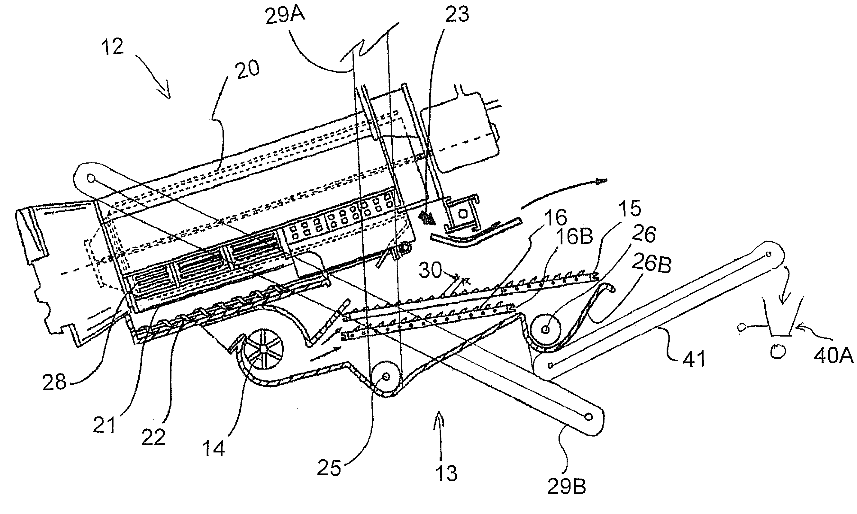
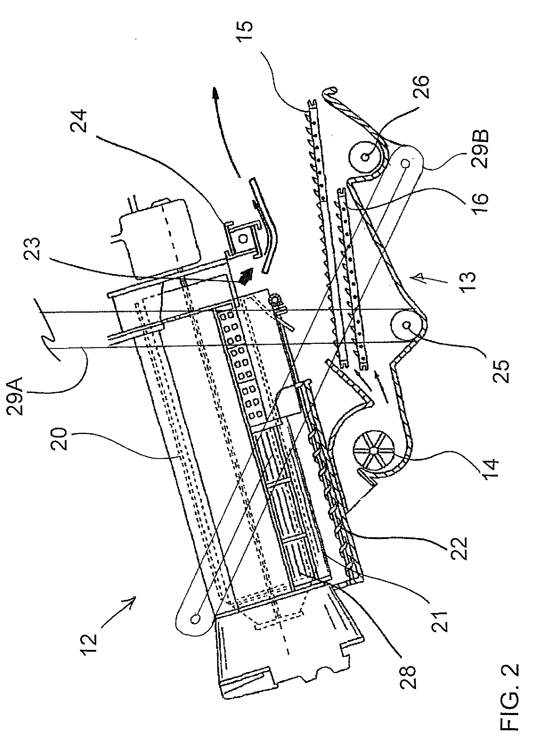
[0056]Referring to the present invention as shown in FIG. 4, the combine threshing system 12 is set-up as in FIG. 3 using the CCM system to separate the corn from the cob and to break the cob into segments.

[0057]The material containing the corn and cobs falls through the concaves 21 to the augers 22 and is conveyed to the upper sieve 15 as in FIG. 3. The upper sieve 15 has the openings 30 set large enough to allow passage of the corn and cobs through the sieve with the remaining chaff exiting the rear of the sieve as before.

[0058]The lower sieve 16 remains installed and screens the grain from the cob segments. All clean grain is moved to the elevator 29A by the cross auger 25. All cob segments and any other material that did not fall through lower sieve 16 exits the rear end 16B of the lower sieve and falls into the tailings trough 26B of the tailings cross auger 26.

[0059]The tailings elevator 29B does not receive the material from the transverse auger 29. An additional conveyor 41 ...

second embodiment

[0060]Referring to FIG. 51 the present harvester is shown. Like the harvester shown in FIG. 4 the combine is set-up to separate the corn from the cob and to break the cob into segments. The cob and corn material falls through the concaves 21 to the augers 22 to be carried to the cleaning system 13.

[0061]Like the harvester in FIG. 4, the lower sieve 16 remains installed and screens the grain from the cob segments. All clean grain is moved to the elevator 29A by the cross auger 25. All cob segments and any other material that did not fall through lower sieve 16 exits the rear end 16B of the lower sieve and falls into the trough 26B as before. The auger 26 moves the cob segments into a secondary separator 40, which removes any remaining grain from the cob sections. The grain passes through the separator and is dropped into the elevator 29B where it is returned to the threshing system 20 for further processing. The cob segments enter the conveyor 41 and are moved to a second storage tan...

third embodiment

[0062]Referring to FIG. 6, the harvester of the present invention is shown. Like the embodiments shown in FIGS. 4 and 5 the combine is set-up to separate the corn from the cob and to break the cob into segments. The cob and corn material falls through the concaves 21 to the transport mechanism 22 to the cleaning system 13. The conventional sieves 15 and 16 remain in place. An additional corn cob sieve 50 is mounted above the upper sieve 15 with openings 51 set large enough to allow passage of the corn and cob material through the sieve with the remaining chaff exiting the rear of the sieve 50.

[0063]The standard upper sieve 15 and the lower sieve 16 below the additional sieve 50 receive the corn and cob material and are set as typical for harvesting corn grain. The auger 25 for the clean grain gathers the grain and moves it out one side of the machine to the clean grain elevator 29A, which deposits the grain in the grain tank 17. A tailings auger 26 returns any grain or chaff or smal...


PUM


Abstract

A combine harvester for corn is adjusted so that the threshing system maintains the grain and cobs together and there is provided a first sieve to separate the grain and cobs from residue material which is discharged from a rear of the first sieve and a second sieve to separate the grain which passes through the second sieve from the cobs which are discharged from a rear end of the second sieve. The grain is transferred to a clean grain tank and the cobs are conveyed to a tank on a towed cart.

Description

[0001]This application claims the benefit under 35 U.S.C. 119 from Provisional Application 60 / 989,859 filed Nov. 23, 2007.[0002]This invention relates to combine harvesting machines arranged for harvesting corn and in particular to an arrangement in the combine harvester to separate the corn cobs from the grain.BACKGROUND OF THE INVENTION[0003]World ethanol production is expected to experience double-digit growth in the next years. Much of the growth is expected to occur in the United States where, with the current pace of expansion, the United States will be the leading producer of ethanol in the near future.[0004]In the United States, ethanol is made almost exclusively from corn. As of December 2006, 16% of the United States corn crop was being used to displace 3% of the nation's annual gasoline consumption. The US government has a stated goal of reducing its dependence on foreign oil by 20%. If this reduction were to come entirely from corn based ethanol it would use up the natio...

Claims


Application Information

Patent Timeline
IPC IPC(8): A01F11/06A01D45/02A01F12/44
CPCA01F11/06
Inventor REDEKOP, LEOMAYERLE, DEAN
Owner REDEKOP ENTERPRISES
Why Eureka
Try Eureka