Thrombectomy catheter with a helical cutter

a helical cutter and catheter technology, applied in the field of thrombocystectomy or atherectomy devices, can solve the problems of time-consuming, traumatic and expensive current transcatheter procedures for opening clogged vessels, and achieve the effects of reducing the risk of clogging and bleeding

Inactive Publication Date: 2009-05-28
TSUKERNIK VLADIMIR B
View PDF13 Cites 77 Cited by
  • Summary
  • Abstract
  • Description
  • Claims
  • Application Information

AI Technical Summary

Benefits of technology

[0020]In accordance with a further aspect of the present invention there is provided a method of removing material from a vessel. The method comprises the steps of providing at least two flexible tubular bodies coaxially located one inside another with the ability of free movement relatively each other, having a proximal ends and a distal ends, two types of cutters attached to the distal end of each tubular bodies and also manual control on the proximal ends of these tubular bodies. The device is advanced transluminally to the destination area until it reaches stenotic lesions. From this point “corkscrew cutter” start the rotational movement with the corresponding longitudinal advance, penetrating the material of the lesion. The “tubular cutter” just follows “corkscrew cutter” performing rotational and longitudinal movement sliding along outside surface of the “corkscrew cutter” shearing the material of lesion by its front edge thus material of the lesion remains locked inside the “corkscrew cutter” area and could be easy removed from the vessel together with the catheter.

Problems solved by technology

Current pharmacological, surgical or trans-catheter procedures for opening clogged vessels can be time consuming, traumatic and expensive as well as most of them remain myriad of small particles of material of destroyed plugs, circulating in the patient's body.

Method used


Image

  • Thrombectomy catheter with a helical cutter
  • Thrombectomy catheter with a helical cutter
  • Thrombectomy catheter with a helical cutter

Examples


Embodiment Construction

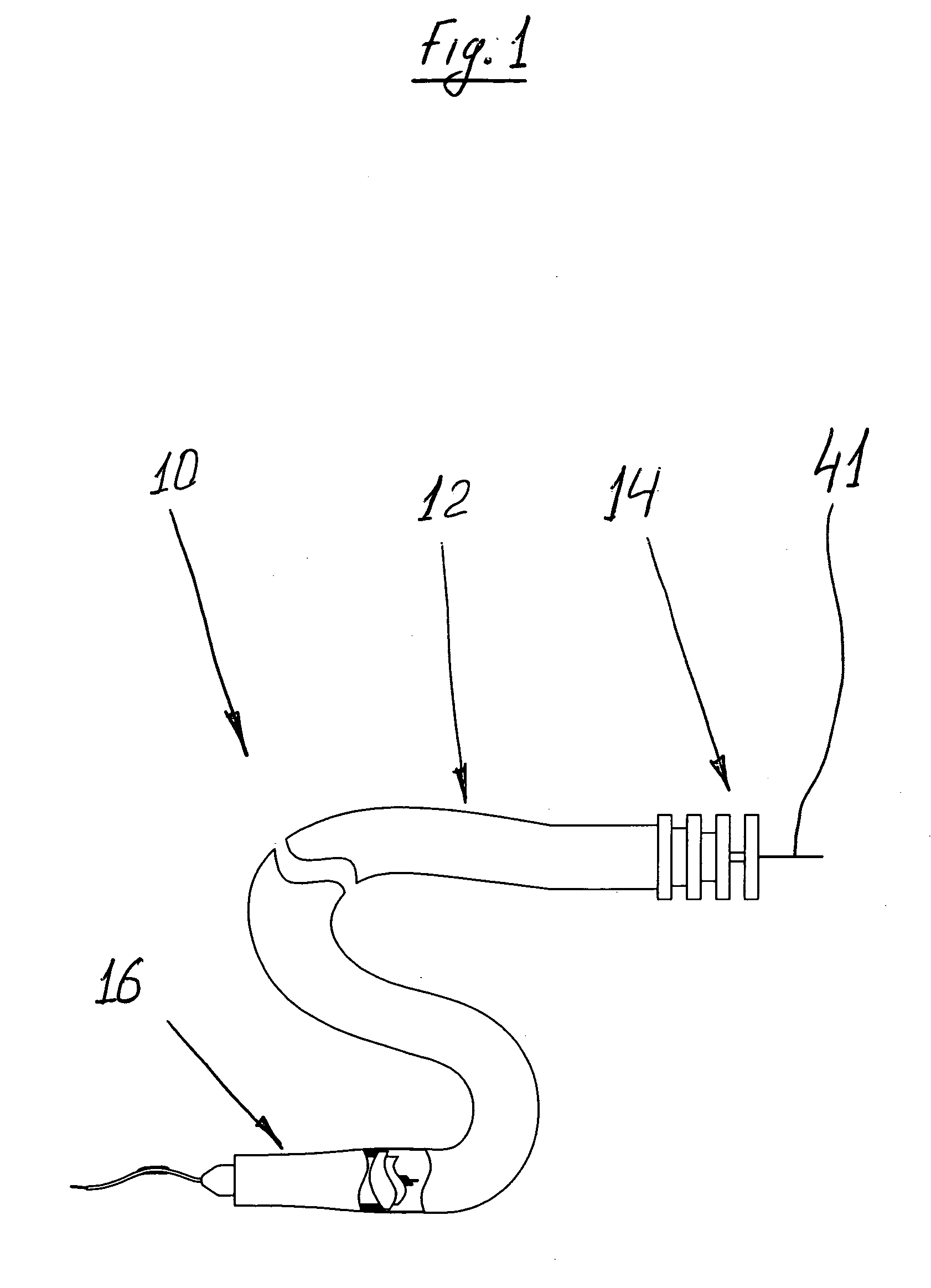
[0035]With reference initially to FIG. 1, a surgical instrument, indicated generally by reference numeral 10 comprises an elongate flexible tubular body 12, having a proximal end 14 and a distal end 16, as well as guide wire 41. A control 18 is preferably provided at or near the proximal end 14 of the tubular body 12 for permitting manipulation of the instrument 10.

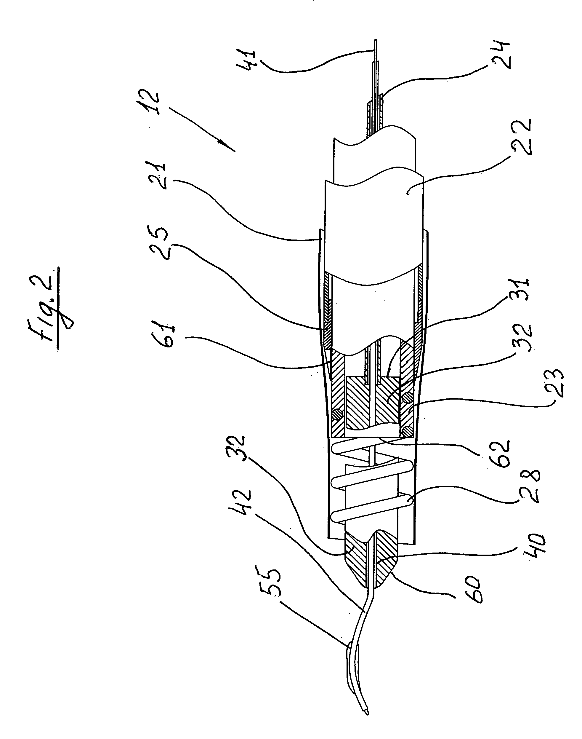
[0036]With reference now to particularly sectioned view of FIG. 2 the tubular body 12 comprises of four tubing coaxially located one inside the others.

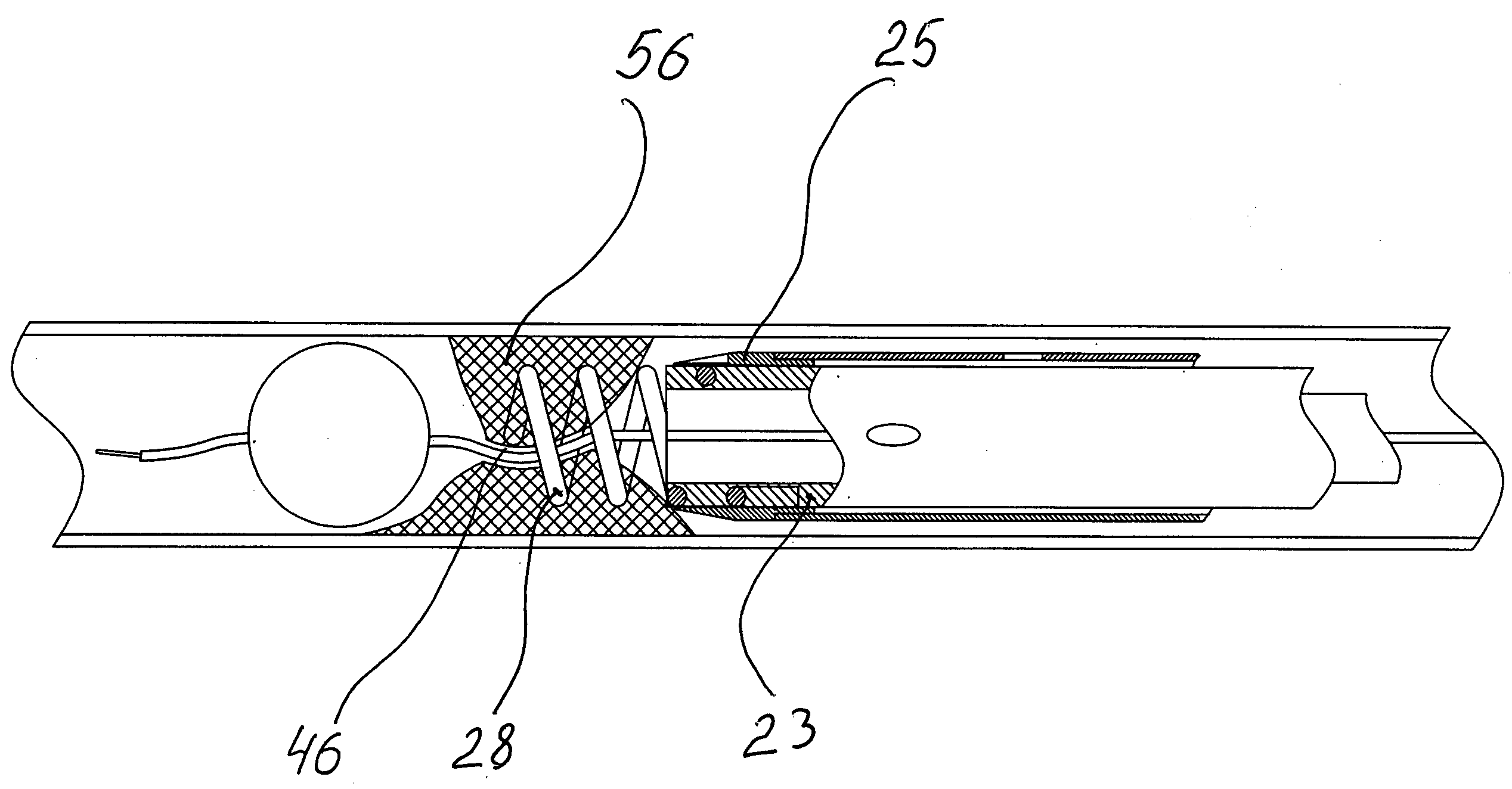
[0037]The “outside tubing”21 which represents the thin wall extrusion (wall thickness ˜0.0005 . . . 001″) comprises the “cutter tubing”22. Inside of the cutter tubing 22 you could find “screw tubing”23 which also comprises central tubing 24.

[0038]With the reference to the FIG. 3 the proximal area 26 of the tubular cutter 25 is permanently connected to the distal portion of the tubing 22 by any available means which aren't discussed. The corkscrew cutter 25 and tubing 22 are...


PUM


Abstract

A thrombectomy catheter including two major members: a cutter of the helically wounded structure and also a cutter of the tubular shape which is located coaxially with the first one. The outside diameter of the helical cutter fits inside diameter of tubular one with a small gap. Thus they cold move independently. Each of them is equipped with the cutting edges on their distal area. Due to this feature the catheter is able to cut off the major portion of the obstacle from a vessel without its fragmentation and safe removing it off the vessel. The catheter is also providing blood perfusion during the surgery as well as provides opportunity for the monitoring of the operation by means of ultrasound, visual etc. devices during the operation. The original flexible design of the helical cutter also prevents the damage of the vessel.

Description

[0001]The present invention generally relates to thrombectomy or atherectomy devices and particularly to thrombectomy catheter devices.[0002]A variety of techniques and instruments have been developed to remove obstructive material from arteries or other body passageways or to repair the ones.[0003]A frequent objective of such techniques and instruments is the removal of atherosclerotic plaques in the patient's arteries. The buildup of these initially fatty deposits characterizes atherosclerosis. It may be referred to as stenotic lesions or plaques while the blocking material may be referred to as stenotic material.[0004]Several kinds of thrombectomy devices have been developed for attempting to remove some or all of such stenotic material. In one type of device, such as that shown in U.S. Pat. No. 5,092,873 a cylindrical housing, carried at the distal end of a catheter, has a portion of its side-wall cut out to form a window into which the stenotic lesion can protrude when the devi...

Claims


Application Information

Patent Timeline
Patent Type & Authority Applications(United States)
IPC IPC(8): A61B17/22
CPCA61B17/320758A61B2017/320741A61B2017/22069A61B2017/22051
Inventor TSUKERNIK, VLADIMIR B.
Owner TSUKERNIK VLADIMIR B
Why Eureka
Try Eureka