Prosthetic heart valve for transfemoral delivery

Inactive Publication Date: 2009-05-28
MEDTRONIC VENTOR TECH
View PDF103 Cites 681 Cited by
  • Summary
  • Abstract
  • Description
  • Claims
  • Application Information

AI Technical Summary

Benefits of technology

[0043]The support frame applies an axial force to the native valve complex from below and above the complex, anchoring the valve prosthesis in place, and inhibiting migration of the prosthetic valve both upstream and downstream. This configuration also allows the valve pro

Problems solved by technology

Such outward radial force typically does not substantially aid w

Method used


Image

  • Prosthetic heart valve for transfemoral delivery
  • Prosthetic heart valve for transfemoral delivery
  • Prosthetic heart valve for transfemoral delivery

Examples


Embodiment Construction

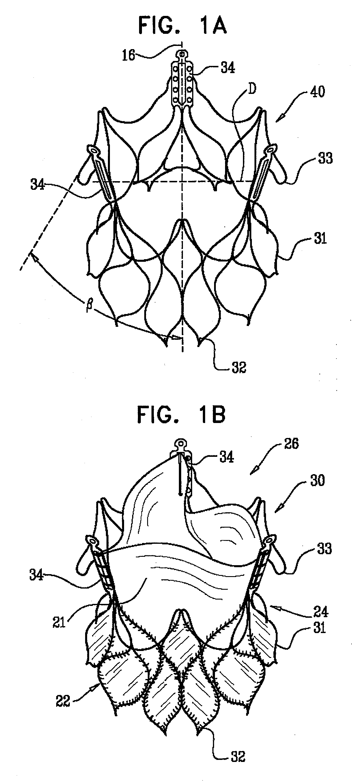
[0074]FIGS. 1A and 1B are schematic illustrations of a valve prosthesis 30, in accordance with an embodiment of the present invention. FIG. 1B shows the prosthesis including a prosthetic valve 21 and a skirt 31, as described below, while FIG. 1A shows the prosthesis without these elements for clarity of illustration. Valve prosthesis 30 comprises a collapsible support frame 40, which typically comprises exactly three commissural posts 34, arranged circumferentially around a central longitudinal axis 16 of valve prosthesis 30. Valve prosthesis 30 further comprises prosthetic downstream valve 21 coupled to commissural posts 34. Valve 21 typically comprises a pliant material. The pliant material is configured to collapse inwardly (i.e., towards central longitudinal axis 16) during diastole, in order to inhibit retrograde blood flow, and to open outwardly during systole, to allow blood flow through the prosthesis.

[0075]Valve prosthesis 30 is configured to be implanted in a native diseas...


PUM


Abstract

Apparatus is provided that includes a valve prosthesis for attachment to a native valve complex of a subject. The prosthesis includes a support frame, which is shaped so as to define a plurality of axial support arches, which extend in a radially outward direction, and are configured to apply, regardless of a rotational orientation of the support frame with respect to the native valve complex, an upstream axial force to a downstream side of one or more native structures selected from the group consisting of: native leaflet tips of the native valve complex, and native valve commissures. The support frame is also shaped so as to define an upstream skirt, which is configured to apply a downstream axial force on an upstream side of the native valve complex. The prosthesis further includes a prosthetic heart valve, coupled to a portion of the support frame. Other embodiments are also described.

Description

CROSS-REFERENCE TO RELATED APPLICATIONS[0001]The present application claims the benefit of: (a) U.S. Provisional Application No. 60 / 978,794, filed Oct. 10, 2007, entitled, “Prosthetic heart valve specially adapted for transfemoral delivery,” and (b) a US provisional application Ser. No. ______, filed Sep. 15, 2008, entitled, “Prosthetic heart valve for transfemoral delivery,” both of which are incorporated herein by reference in their entireties.FIELD OF THE INVENTION[0002]The present invention relates generally to prosthetic heart valves, and specifically to prosthetic heart values configured for transfemoral delivery.DESCRIPTION OF THE RELATED ART[0003]Aortic valve replacement in patients with severe valve disease is a common surgical procedure. The replacement is conventionally performed by open heart surgery, in which the heart is usually arrested and the patient is placed on a heart bypass machine. In recent years, prosthetic heart valves have been developed which are implanted...

Claims


Application Information

Patent Timeline
IPC IPC(8): A61F2/24A61B19/00
CPCA61F2/2418A61F2220/0016A61F2/2436A61F2/2433
Inventor TUVAL, YOSIKOVALSKY, IGOR
Owner MEDTRONIC VENTOR TECH
Why Eureka
Try Eureka