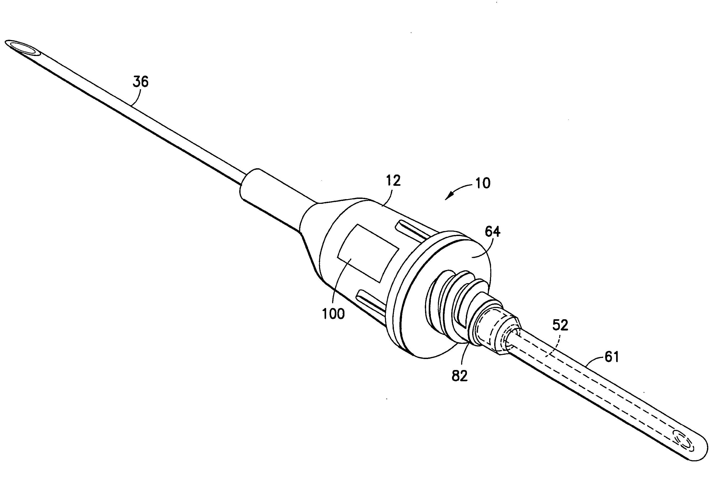
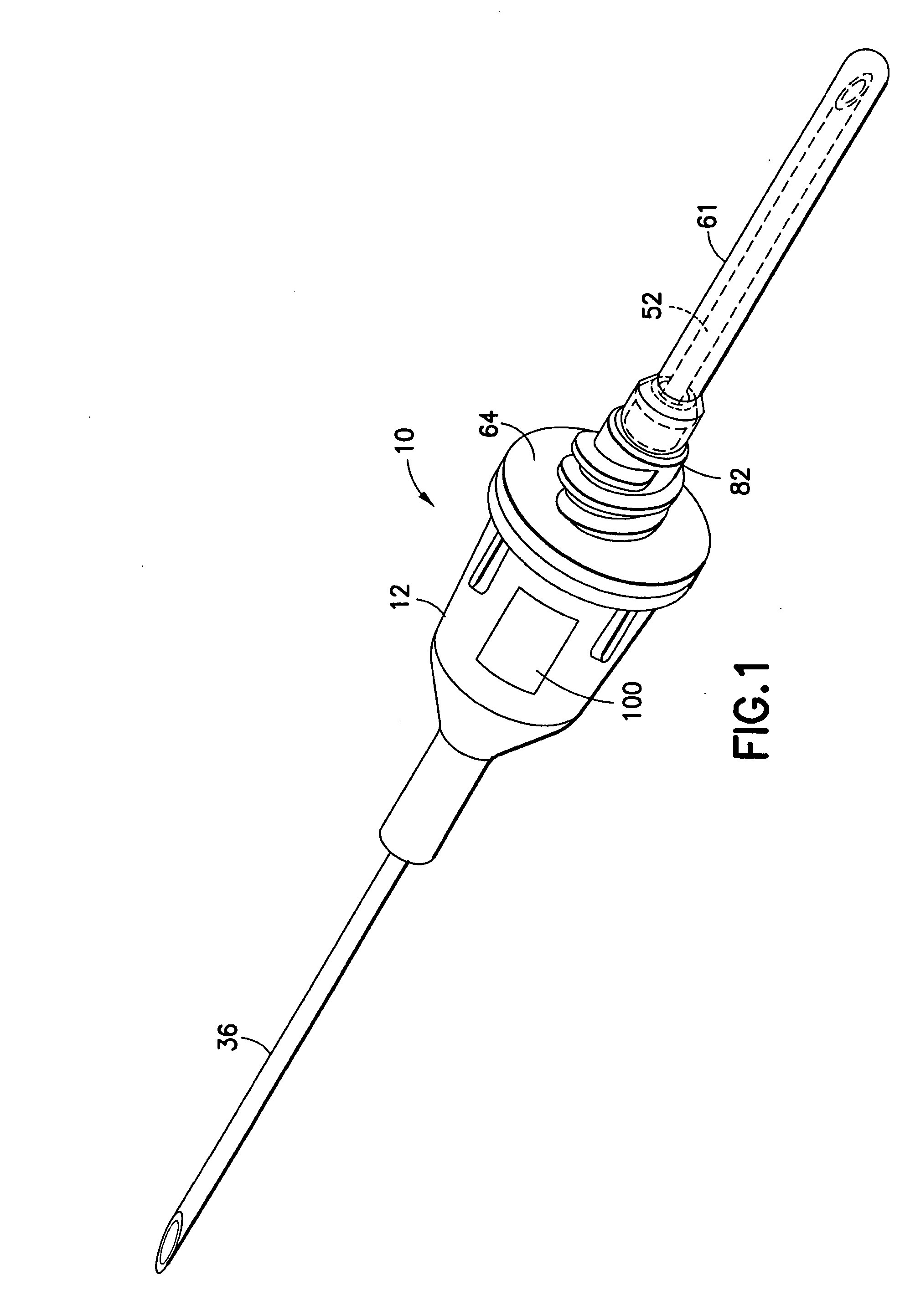
[0011] The invention is a self-venting blood collection needle assembly for the extraction of at least one fluid sample into an
evacuated container for
laboratory testing, this blood collection needle assembly providing a clear or translucent flashback chamber for blood to flow into, for
visualization by the user to confirm successful
vein entry. The self-venting mechanism permits escape of air during use, and which, typically, also prevents an outflow of fluid, such as blood. As used herein, venting mechanism indicates one or more features or elements that provide venting of air, but which, typically, prevent fluid from passing through. Thus, air under
venous pressure will be allowed to escape from the blood collection needle assembly until blood reaches the venting mechanism. The venting mechanism then will seal, or prevent
blood flow around or through it, to allow blood to be collected into evacuated collection tubes or into other appropriate blood collection receptacles. The invention thus provides good flash
visualization within the flashback chamber, without affecting accepted blood collection processes. A variety of venting mechanisms, venting media and venting locations are suitable, as set forth below.
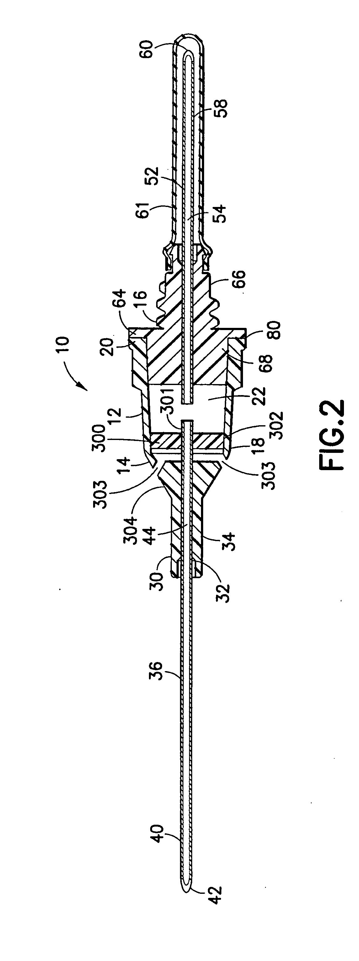
[0013] In one embodiment, the venting mechanism is located in the hub within the flashback chamber. The use of the 2 cannula design or the notched single cannula is appropriate with this configuration. The venting mechanism thereby provides communication between the fluid passage and the surrounding environment through the hub.
[0014] In another embodiment, the venting mechanism is located beyond the non-patient cannula proximal end, which means that the air passes through the non-patient cannula proximal end from which blood is drawn, and then through the vent. A single cannula with no notch is appropriate here, however all cannula configurations can be used. Specifically, air is vented from the fluid passage and out of the non-patient cannula proximal end where it further flows through the space between needle exterior and multiple sample sleeve. The air then flows through the venting mechanism, which may be at the non-patient barb, the non-patient hub thread, the non-patient hub body, the multiple sample sleeve, or other location or combination of locations that are beyond the non-patient cannula proximal end. The collection tube, which is applied at the non-patient cannula proximal end, draws blood from only the fluid passage and not from the vent space. This embodiment thus enables blood to flow through the entire collection path. It also avoids the
blood specimen coming in contact with the vent, which could potentially cause
platelet activation,
contamination or other undesirable result. It also avoids air being sucked back into the fluid passage when the
evacuated tube is applied. It should also be noted that this embodiment necessitates a smaller flash chamber when compared to the previous embodiment where the vent is located in the hub.
[0015] Another embodiment of this invention has a venting mechanism comprised of a unified hub that is at least partially constructed of porous material such as a sintered plastic,
ceramic or
metal. The porous material can be arranged to provide venting of air either before that air enters the non-patient cannula, or after the air flows through the non-patient cannula, out the proximal end, and into the space between the cannula and a multiple sample sleeve. The porous material provides venting of the air but blocks leakage of the blood. In the typical embodiment, the porous material is hydrophobic. The porous material may further contain materials that swell upon
wetting to further contain the blood. Other venting methods are also possible. The internal passage wall's surface may be coated with a
sealant to prevent
contamination of the blood sample by the porous material. This embodiment enables blood to flow through the entire collection path. Optionally, the hub can be permanently bonded to a tube holder obviating the need or inconvenience of threaded connections. Bonding to the holder may be accomplished by
solvent,
welding, heat, pressure or and other convenient means or combination thereof. Such an integrated device is highly efficient to manufacture, and promotes safe
medical practice by having the holder be discarded with the needle.
[0016] In a further embodiment, the venting mechanism involves venting air through a side opening located in the hub to the exterior, where the opening is covered by a venting material having a shape, which mechanically holds the venting material in or on the opening. Preferably, the vent material is hydrophobic such that the
surface tension also prevents leakage. The vent media material in this embodiment typically has an elastic property and shape such that spring energy holds the vent material onto the device. For example, it is possible to use a C-shaped vent in which
distortion of the shape is required for the vent to stretch over the receiving structure on the hub. Once the vent is placed over the receiving structure, it is released and fully maintained in place using its own resiliency and in absence of bonding materials such as epoxies, which could be disadvantageously absorbed into the vent. The vent mechanism of this embodiment could alternatively involve first compressing a vent material, placing the material into the opening, and releasing the vent material to expand into the opening. This embodiment enables efficient
mass production.

