Method of controlling an irrigation system

a technology of irrigation system and irrigation system, applied in non-electric variable control, process and machine control, instruments, etc., can solve the problems of excess water used and wasted, rain sensors that do not measure the necessary requirements for irrigation, and cannot adjust, so as to eliminate excessive water use, improve cost efficiency, and easy to understand

Inactive Publication Date: 2009-05-28
CRAWFORD JEFFREY A
View PDF3 Cites 31 Cited by
  • Summary
  • Abstract
  • Description
  • Claims
  • Application Information

AI Technical Summary

Benefits of technology

[0011]In view of the foregoing, it is the primary object of the present invention to provide a method of controlling an irrigation system with the use of ET that is more easily understood by the average end user of an irrigation system. By the average end user being able to understand how the system works, ET could be used by the majority of irrigation users. It is therefore one purpose of the present invention to provide an improved method of controlling an irrigation system wherein the watering event is defined by ET. The end user could have any type of weather station to automatically provide ET. The end user could manually input ET. The end user could program ET by hist

Problems solved by technology

It has no way of calculating the amount of water necessary for the watering cycle.
However, rain sensors do not measure the necessary requirements for irrigation and make no adjustments to run times. The system is on or off.
In FIG. 1, the shaded areas represent a very common, but incorrect watering practice, where the irrigation system is programmed by season rather than actual ET data.
When controllers are not adjusted as water demand decreases and increases, excess water is used and wasted.
Water management is a critical issue for water conservation thro

Method used


Image

  • Method of controlling an irrigation system
  • Method of controlling an irrigation system
  • Method of controlling an irrigation system

Examples


example 1

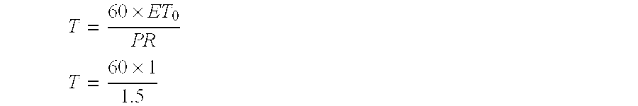
[0030]Calculation of run time to apply 1″ of water where PR equal to 1.5″, where K equal to 0.7 and where IE equal to 80 percent.

T=60×ET0×KCPR×IET=60×1×.71.5×.8[0031]T=35 minutes

example 2

[0032]Calculation of run time based on ET equal to 0.2, PR equal to 1.5″, K equal to 0.7 and IE equal to 80 percent.

T=60×.2×.71.5×.8[0033]T=7 minutes

example 3

[0034]Calculation of run time based on application of 1″ of water with precipitation rate equal to 1.5″, K equal to 0.7 and IE equal to 80 percent multiplied by ET equal 0.2.[0035]T=35 minutes time calculated to provide 1″ with values set above x ET[0036]T=35×0.2[0037]T=7 minutes

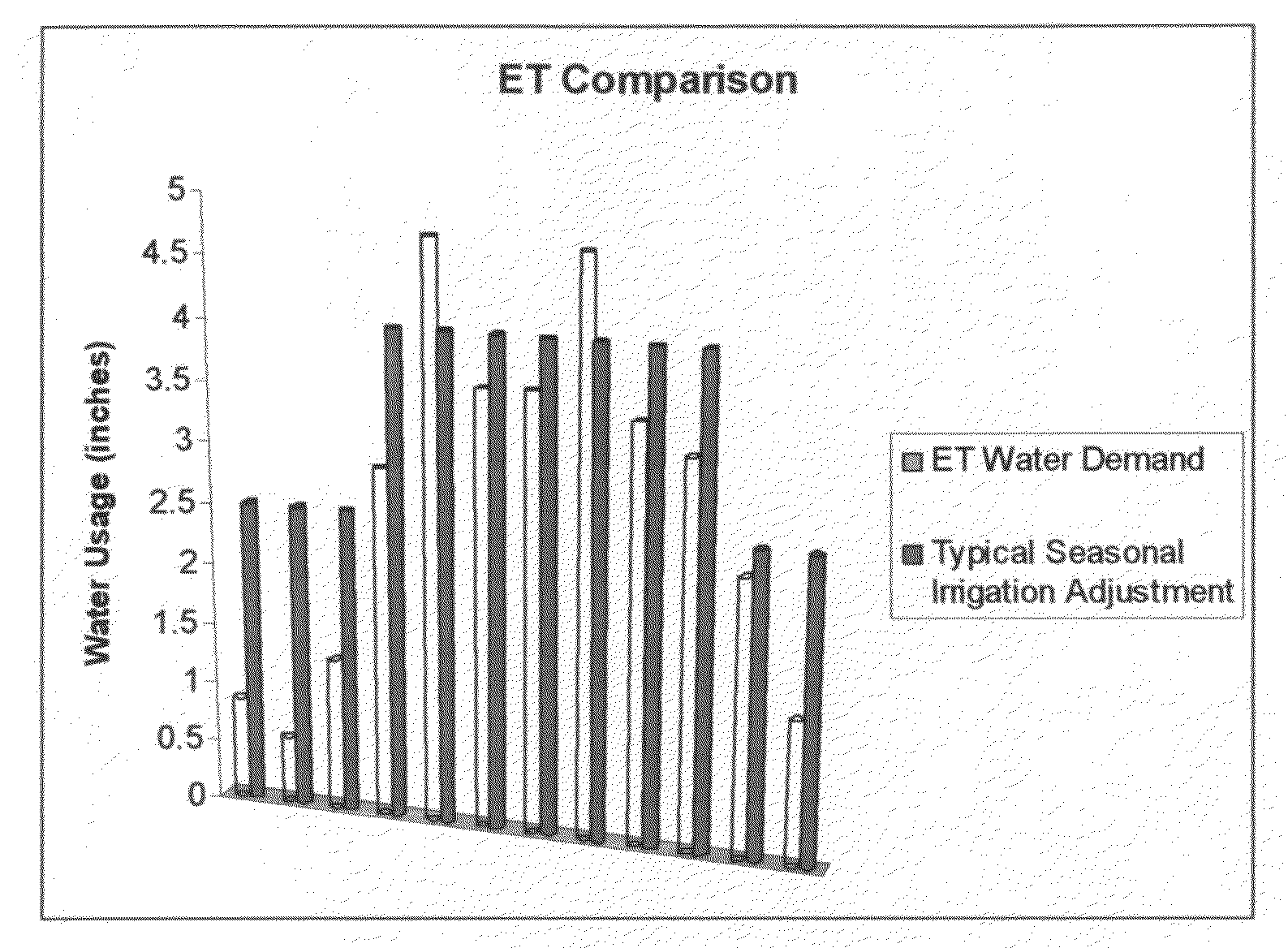
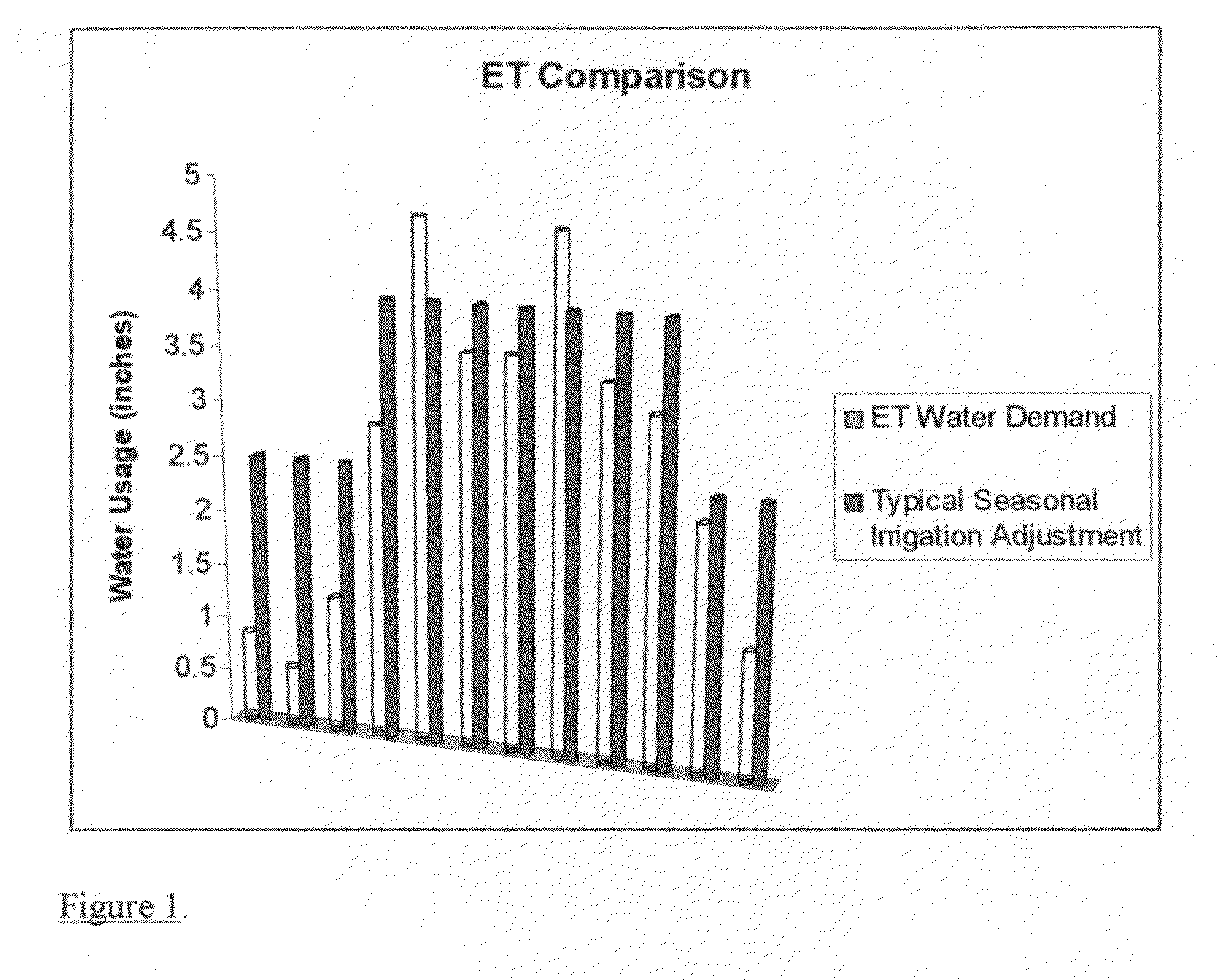
[0038]The above examples are to prove that ET can be used as a percentage against run time and produce the same result as using precipitation rate calculation with the use of irrigation efficiency and landscape coefficient. Example 1 shows what the run time would need to be to apply 1″ of water. Example 2 shows what the run time would be using a precipitation rate based on 1.5″ of water and 0.2 ET value. Example 3 shows run time based at 1″ of water is than multiplied by ET to obtain the same value as defined in example 2. By calculating run times based on 1″ application of water with irrigation efficiency and landscape coefficients, ET can become a percentage of run time to make adjustment.

[0039]As shown ab...


PUM


Abstract

The present invention is a method of controlling an irrigation system that minimizes the amount of irrigation water applied with the use of evapotranspiration (ET) to adjust the irrigation controller. By basing the irrigation program on run times which equal a specific amount of water, ET can be used as a percentage to adjust the amount of water applied during an irrigation cycle. By setting a run time to equal 1″ of rainfall ET can be used as a multiplier against the run time to make the correct adjustment to provide required water. By setting the amount of water to be applied to 2″ or any other amount would need an additional multiplier added to make the proper adjustment. Adjustments for landscape coefficient and distribution uniformity would be placed in run time formula based on use of ET set at 1″. The adjusted run time would be the input into the control system.

Description

CROSS-REFERENCE TO RELATED APPLICATIONS[0001]Not ApplicableSTATEMENT REGARDING FEDERALLY SPONSORED RESEARCH OR DEVELOPMENT[0002]Not ApplicableREFERENCE TO SEQUENCE LISTING, A TABLE, OR A COMPUTER PROGRAM LISTING APPENDIX[0003]Not ApplicableTHE FIELD OF INVENTION[0004]The present invention relates generally to methods of controlling an irrigation system. More specifically, the present invention relates to methods of controlling an irrigation system to minimize the amount of irrigation water applied to a turf or crop while still meeting the crop or turf's water requirements. Still more specifically, the present invention relates to how ET is used to determine the amount of watering time necessary in an irrigation cycle to apply the proper amount of water.BACKGROUND[0005]A feature in place to help conserve water is the water budget component available on the majority of new irrigation controllers. Solid state controllers have used water budget for many years. The use of water budget al...

Claims


Application Information

Patent Timeline
IPC IPC(8): G05D7/06G05B9/02
CPCA01G25/16Y02A40/10
Inventor CRAWFORD, JEFFREY A.
Owner CRAWFORD JEFFREY A
Why Eureka
Try Eureka