Low residence combustor fuel nozzle

a combustor and fuel nozzle technology, applied in the direction of machines/engines, mechanical equipment, lighting and heating apparatus, etc., can solve the problems of high emissions, damage to the combustion system, auto ignition, etc., and achieve the effect of maintaining combustor performance and reducing the residence time of fuel and air mixtur

Active Publication Date: 2009-06-04
ANSALDO ENERGIA SWITZERLAND AG
View PDF10 Cites 22 Cited by
  • Summary
  • Abstract
  • Description
  • Claims
  • Application Information

AI Technical Summary

Benefits of technology

[0006]The present invention provides embodiments for an apparatus and associated method for reducing the residence time of a fuel and air mixture in a gas turbine combustor while maintaining combustor performance with respect to ignition and emissions. In an embodiment of the present invention a fuel nozzle for a gas turbine combustor is disclosed having a centerbody, a plurality of swirlers extending from the centerbody, and an outer shroud extending from the centerbody and radially encompassing the swirlers, thereby creating a passageway between the centerbody and the outer shroud. Air is drawn into the passageway and mixes with fuel from the centerbody as the air and fuel exit the fuel nozzle.

Problems solved by technology

However, maintaining the fuel and air mixture in the premixer for an extended period of time at an elevated temperature and pressure can lead to auto ignition.
In the event auto ignition of the fuel and air mixture occurs, damage to the combustion system, high emissions levels, and elevated combustion dynamics are some possible and undesirable results.

Method used


Image

  • Low residence combustor fuel nozzle
  • Low residence combustor fuel nozzle
  • Low residence combustor fuel nozzle

Examples


Embodiment Construction

[0021]The subject matter of the present invention is described with specificity herein to meet statutory requirements. However, the description itself is not intended to limit the scope of this patent. Rather, the inventors have contemplated that the claimed subject matter might also be embodied in other ways, to include different steps or combinations of steps similar to the ones described in this document, in conjunction with other present or future technologies. Moreover, although the terms “step” and / or “block” may be used herein to connote different elements of methods employed, the terms should not be interpreted as implying any particular order among or between various steps herein disclosed unless and except when the order of individual steps is explicitly described.

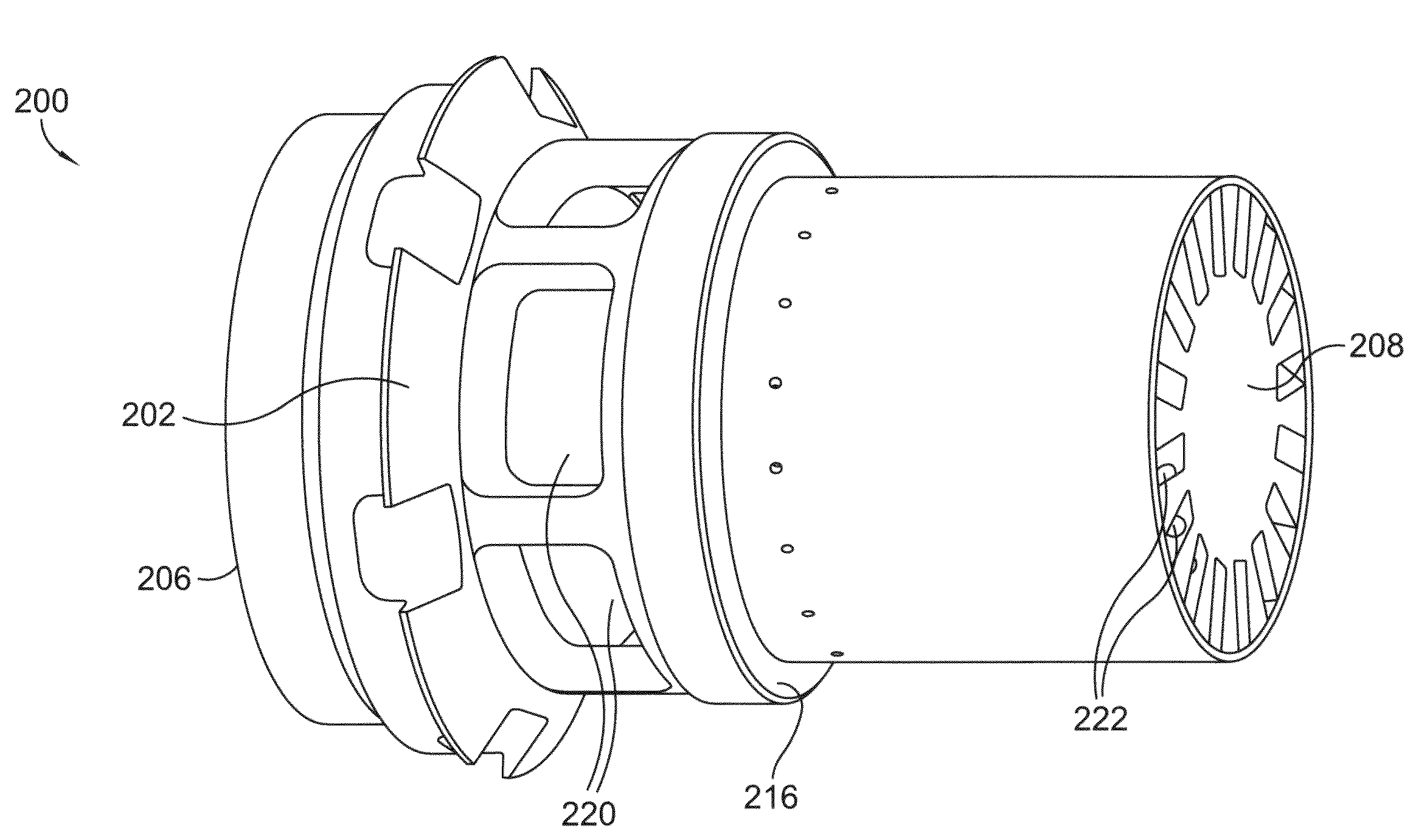
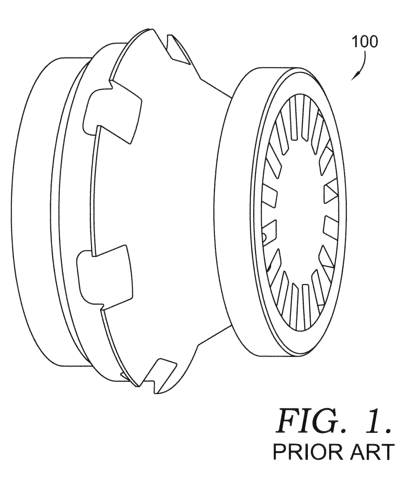
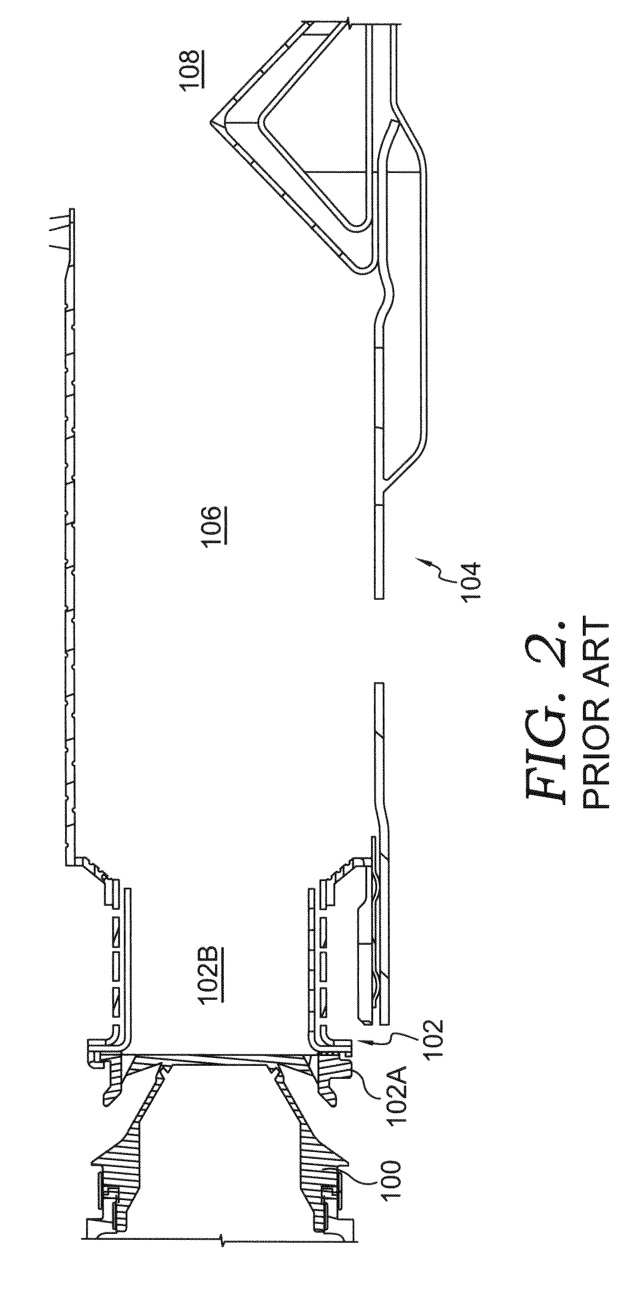
[0022]Referring initially to FIG. 1, a perspective view of a fuel nozzle 100 in accordance with the prior art is shown. In FIG. 2, the fuel nozzle 100 is shown in cross section as installed in an end cap 102, whi...


PUM


Abstract

Embodiments for an apparatus and associated method for reducing the residence time in a gas turbine combustor are disclosed. The embodiments of the present invention comprise a fuel nozzle that extends to a downstream plane of an end cap for a combustion liner where the axial distance of the premixer is reduced, however the swirl for mixing the fuel and air, is increased. As a result, the mixing of the fuel and air is essentially unchanged, thereby allowing higher air pressures and operating temperatures within the premixer without inducing auto-ignition.

Description

CROSS-REFERENCE TO RELATED APPLICATIONS[0001]Not Applicable.STATEMENT REGARDING FEDERALLY SPONSORED RESEARCH OR DEVELOPMENT[0002]Not Applicable.TECHNICAL FIELD[0003]The present invention relates to gas turbine engines. More particularly, embodiments of the present invention relate to an apparatus and a method for reducing a residence time in a combustor of a gas turbine engine.BACKGROUND OF THE INVENTION[0004]Gas turbine engines operate to produce mechanical work or thrust. Land-based gas turbine engines typically have a generator coupled thereto for the purposes of generating electricity. In operation, fuel is directed through a fuel nozzle where it mixes with compressed air in the combustor and is ignited to form hot combustion gases. These hot combustion gases then pass through the turbine, thereby driving the turbine, which is coupled to a compressor.[0005]The fuel and air mixture is present in a premixer portion of the combustor for only a relatively brief period of time. Howev...

Claims


Application Information

Patent Timeline
Patent Type & Authority Applications(United States)
IPC IPC(8): F23R3/28
CPCF23R3/286F23R3/14
Inventor SULLIVAN, DANIEL J.STUTTAFORD, PETERKRAFT, ROBERT J.OUMEJJOUD, KHALIDCHEN, YAN
Owner ANSALDO ENERGIA SWITZERLAND AG
Why Eureka
Try Eureka