Radio frequency signal acquisition and source location system

a radio frequency signal and source location technology, applied in the direction of using reradiation, burglar alarm mechanical actuation, instruments, etc., can solve the problems of inability to provide a specific location and/or direction of travel, and inability to accurately measure the associated flight time with the required resolution

Active Publication Date: 2010-09-09
RF CONTROLS
View PDF60 Cites 39 Cited by
  • Summary
  • Abstract
  • Description
  • Claims
  • Application Information

AI Technical Summary

Benefits of technology

[0023]As described herein below, it is highly advantageous for the antenna 14 to generate a narrow beam pattern. Although other types of narrow beam antenna 14 may be applied, an exemplary antenna type, is the phased array antenna 14. Phased array antennas 14, for example including a power splitter 18 dividing an interrogation signal from the RF transceiver 12 between an array of antenna element(s) 20 such as dipole, patch or other form of radiator antenna element(s) 20 may be formed as compact planar panels. To minimize interference and or for specific operating frequency requirements, the antenna 14 may be provided with a transmit antenna element 20 separate from a receive antenna element 20 and or respective arrays of transmit and receive antenna element(s) 20.
[0047]To obtain higher resolution points proximate a likely response signal location, the beam sweep rate and or increment may be adjusted to increase the residence time at a particular RF signal direction of interest. For example, when a response signal is detected, the next scan increment may be reduced and the residence time increased. Similarly, where no response signal has been detected, the scan increment may be increased and the dwell time reduced until a further response signal is detected. Further, as multiple scans are completed, the approach towards areas of the previous scan that had response signal activity may initiate similar sweep increment reductions and scan dwell time increases to attempt to identify with greater resolution the specific bounds of the scan that indicate specific signal identification response signal activity. By focusing on identified areas of signal activity and less upon areas of no or rare activity, the overall scan rate may be maximized. To reduce the load these types of logic operations may apply to the local processor28 and data storage 26 bandwidth they may be placed at the edge server 34 or master SASL module10, if present, and areas of the scan designated for higher or lower interest transmitted back to the respective electronic steering circuit.

Problems solved by technology

Signal interference and false reflected or ghost signals frustrate the use of radio finding systems in smaller target areas.
However, especially when applied to relatively short distances, the accurate measurement of the associated flight times with the required resolution may be cost prohibitive.
This does not provide a specific location and / or direction of travel, other than by transient association between the tags or tagged items and the location of the reader at the time of interrogation.
Multiple gateways and or portals may be applied to improve the general location resolution, but the number of gateways and or portals required to obtain a worthwhile location accuracy renders a high resolution solution using large numbers of gateway installations cost prohibitive.
Also, neighboring gateways create significant interrogation signal interference issues.
A drawback of presence / passage gateways is that the residence time of the RFID tag(s) within the detection field may be relatively short and at the same time as large numbers of other RFID tags, such as where a pallet stacked with RFID tagged items moves past the gateway, during this short residence period it may be difficult to accurately interrogate and then differentiate between each of the resulting response signals and the full data content they each may transmit.
Widely used as theft protection systems, EAS tags have the drawback of alarming only as the EAS tag passes through a gateway, typically located at the door of a store.
In many jurisdictions, the law does not permit challenging a person once beyond the store property, which frustrates shop-lifting enforcement / property recovery.

Method used


Image

  • Radio frequency signal acquisition and source location system
  • Radio frequency signal acquisition and source location system
  • Radio frequency signal acquisition and source location system

Examples


Embodiment Construction

[0019]The inventors have analyzed presently available signal acquisition and source location technology and recognized that a cost effective solution was not available for three dimensional signal location within a defined zone. For example with respect to RFID signals, the inventors recognized that there was a collective mindset in the signal acquisition and source location technology space that RFID technology in particular is applicable only with respect to gateway type exit / entry and or general presence detection and reporting function(s).

[0020]Further, the inventors have recognized that multiple gateway solutions for determining a general signal direction and or speed determination are unnecessarily complex, impractical and cost prohibitive.

[0021]Therefore, the inventors have developed an RF signal intelligent tracking and control system (ITCS) 5 that utilizes one or more signal acquisition and source location (SASL) module(s) 10.

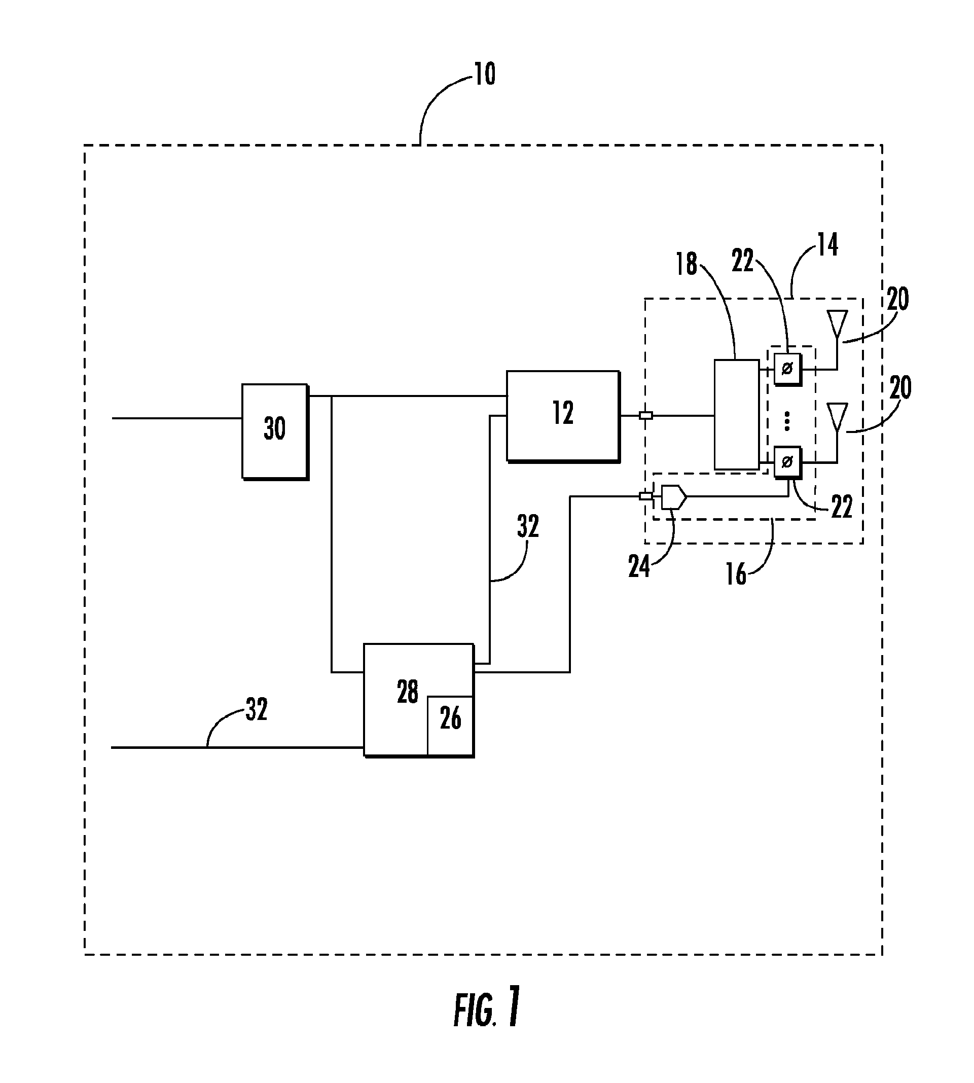
[0022]As shown in FIG. 1, an exemplary SASL modu...


PUM


Abstract

A radio frequency signal acquisition and source location system, including a first signal acquisition and source location module comprising an RF transceiver coupled to an antenna, the antenna provided with a electronic steering circuit. The antenna operative to launch an interrogation signal, the interrogation signal steerable by an electronic steering circuit. A processor operatively coupled to the RF transceiver and the electronic steering circuit, the processor provided with a data storage for storing a signal data record for each of at least one response signal(s) received by the RF transceiver(s). The signal data record including a signal identification, a received signal strength indicator and an RF signal direction along which respective signal(s) are received by the antenna, the RF signal direction derived from the electronic steering circuit. A position logic operative upon the data record(s) deriving a three dimensional signal origin location of each response signal.

Description

CROSS REFERENCE TO RELATED APPLICATIONS[0001]This application claims the benefit of U.S. Provisional Patent Application No. 60 / 993,418, titled “Steerable Phase Array Antenna RFID Tag Locator and Tracking System”, filed by Graham P. Bloy on Sep. 11, 2007 and hereby incorporated by reference in its entirety.BACKGROUND[0002]1. Field of the Invention[0003]The invention generally relates to Radio Frequency (RF) signal acquisition and source location. More particularly, the invention relates to RF signal acquisition and source location in three dimensions.[0004]2. Description of Related Art[0005]Prior signal acquisition and source location systems, for example radio direction finding systems typically operate on a triangulation basis, where location accuracy is dependent upon the number of signal reception points and their relative distance away from each other and the signal source. Signal interference and false reflected or ghost signals frustrate the use of radio finding systems in sma...

Claims


Application Information

Patent Timeline
Patent Type & Authority Applications(United States)
IPC IPC(8): G08B13/14
CPCG01S5/0215G01S5/04G01S5/12G01S13/76G01S13/878G08B13/2462G06K2017/0045H01Q1/2216H01Q3/36G06K7/01G06K7/10079G01S5/0218
Inventor BLOY, GRAHAM P.PIERCE, MATTHEW E.HOFER, RUSSELL
Owner RF CONTROLS
Why Eureka
Try Eureka