Automotive fuel tank

a fuel tank and auto technology, applied in the field of fuel tanks, can solve the problems of increasing the weight of the molded fuel tank, separating the abutment surface b, /b> from the inner surface, etc., and achieve the effect of increasing the distance between the apexes of the adjacent elongated projections

Inactive Publication Date: 2009-06-04
FTS
View PDF12 Cites 49 Cited by
  • Summary
  • Abstract
  • Description
  • Claims
  • Application Information

AI Technical Summary

Benefits of technology

[0020]The abutment portion has formed thereon the abutment surface which tightly sticks to the inner surface of the outer wall of the fuel tank and the elongated projection which projects from the abutment surface, whose cross section at the distal end portion is of triangular shape and which penetrates into the interior of the outer wall of the fuel tank. Because of this, the abutment surface tightly sticks to the inner surface of the outer wall of the fuel tank, and a maximum value of a dimension by which the elongated projection penetrates into the interior of the outer wall of the fuel tank can be controlled, and the elongated projection penetrates into the interior of the outer wall of the fuel tank, so as to be strongly fusion bonded to the outer wall of the fuel tank.
[0043]According to the ninth aspect of the invention, the bottom face is formed between the projecting portions. Therefore, the distance between the apexes of the adjacent elongated projections can be increased as compared with the abutment portion in which the bottom face is not formed between the adjacent projecting portions. Consequently, when the outer wall of the fuel tank and the elongated projections are fusion bonded to each other and the apexes of the elongated projections penetrate into the interior of the outer wall, the fused outer wall is allowed to more easily enter between the elongated projections than the structure in which the bottom face is not formed between the projecting portions and the abutment portion can strongly be fusion bonded to the outer wall.

Problems solved by technology

In this case, however, since the built-in part 120 is set in the resin frame and is then secured to the inner circumferential surface of the outer wall of the fuel tank, labor hours have to be involved in cutting to remove the resin frame after the fuel tank has been molded, and with a small built-in part 120, a large resin frame has to be used, often resulting in a case where the weight of the molded fuel tank is increased.
Thus, there occurs only weak adhesion therebetween, and fusion bonding strength is not sufficiently large, leading to a fear that the abutment surface 233 may be separated from the inner surface of the parison 208 due to vibration of fuel in the fuel tank or expansion of the fuel tank.

Method used


Image

  • Automotive fuel tank
  • Automotive fuel tank
  • Automotive fuel tank

Examples


Embodiment Construction

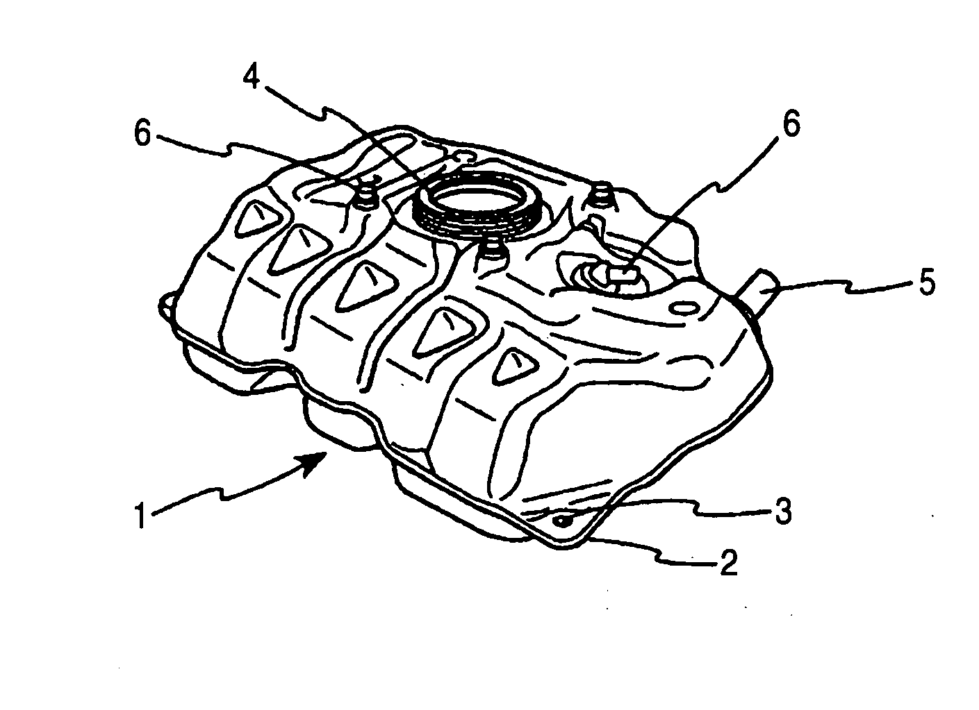
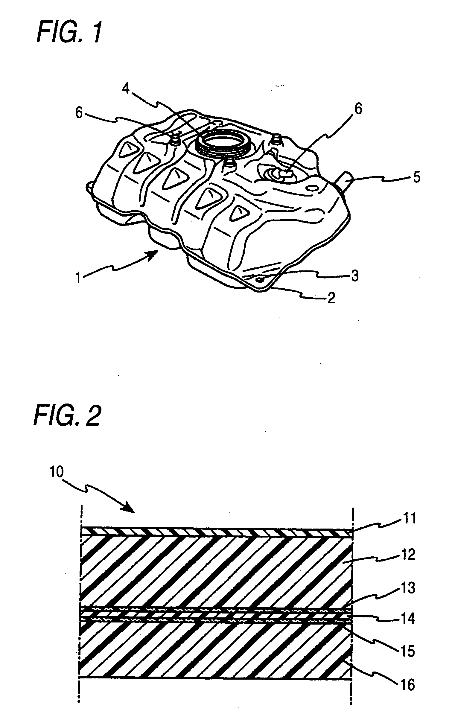
[0060]An automotive fuel tank 1 of an embodiment of the invention will be described based on FIGS. 1 to 14. FIG. 1 is a perspective view of a fuel tank 1 of an embodiment of the invention, and FIG. 2 is a partial sectional view of an outer wall 10 of the fuel tank 1 which is made from a thermoplastic synthetic resin, which shows the configuration of a multi-layer construction of the outer wall 10.

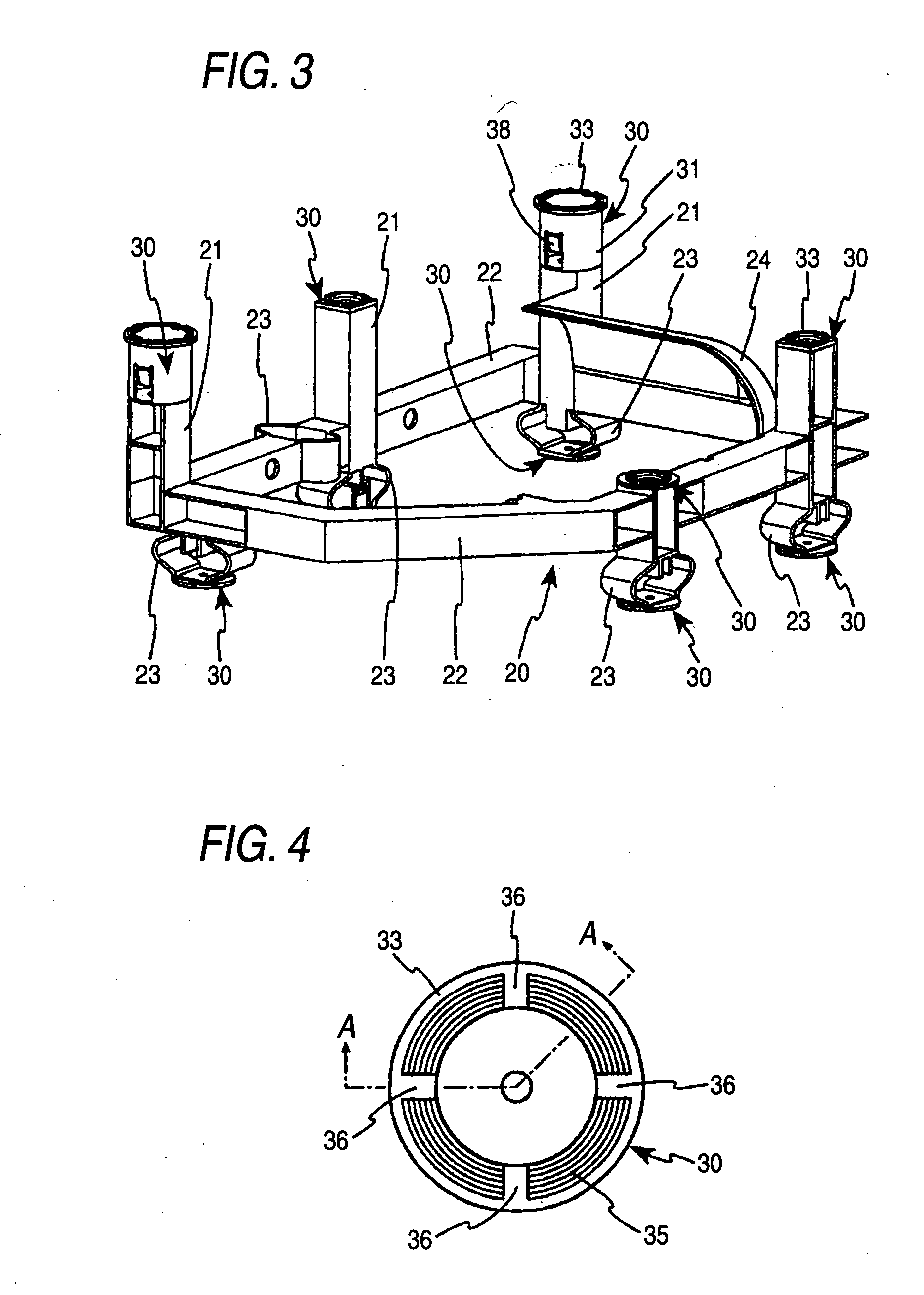
[0061]FIG. 3 is a perspective view showing an example of a built-in part 20 of the fuel tank 1.

[0062]FIGS. 4 to 11 are drawings showing mounting members 30 for attaching the built-in part 20 of the fuel tank 1 to an inner surface of an outer wall of the fuel tank. FIGS. 12 to 14 are drawings showing blow molding steps for fabricating the fuel tank 1.

[0063]As is shown in FIG. 1, the fuel tank 1 which is fabricated in the embodiment of the invention has a pump unit mounting hole 4 formed in an upper surface of the tank for ingress and egress of a fuel pump (not shown) into and from the fuel t...


PUM

PropertyMeasurementUnit
thicknessaaaaaaaaaa
thicknessaaaaaaaaaa
heightaaaaaaaaaa

Abstract

An automotive fuel tank is provided in which a plurality of mounting members are provided on a built-in part which are fusion bonded to an inner surface of an outer wall of the fuel tank so as to attach the built-in part in place in the fuel tank. An abutment portion is formed on the mounting member which is brought into abutment with an inner surface of the outer wall of the fuel tank. The abutment portion has formed thereon an abutment surface which is made to tightly stick to the inner surface of the outer wall of the fuel tank and elongated projections which project from the abutment surface, whose cross section at their distal end portions is of triangular shape and which penetrate into an interior of the outer wall of the fuel tank, and a height of an apex of the elongated projection from the abutment surface is in the range of 30% to 70% of a thickness of the outer wall of the fuel tank.

Description

BACKGROUND OF THE INVENTION[0001]1. Field of the Invention[0002]The present invention relates to a fuel tank made from a thermoplastic synthetic resin and more particularly to an automotive fuel tank whose outer wall is formed from a thermoplastic synthetic resin through blow molding and which has a built-in part in an interior thereof.[0003]2. Related Art[0004]Conventionally, metallic fuel tanks were used as fuel tanks for motor vehicles and the like. In recent years, however, fuel tanks made from thermoplastic synthetic resins have been in use due to thermoplastic resin materials being light in weight to satisfy increasing demands for vehicles which are light in weight, being free from rust, being easy to be molded into desired shapes.[0005]A blow molding approach has been used in many cases in fabricating automotive fuel tanks from thermoplastic resins because the blow molding approach facilitates the molding of hollow objects. In the blow molding approach, a parison made of a mo...

Claims


Application Information

Patent Timeline
Patent Type & Authority Applications(United States)
IPC IPC(8): B60K15/03
CPCB29C49/04B29C49/20B29C2049/2013B60K15/077B29L2031/7172B60K15/03177B29C2049/4807
Inventor AOKI, TOMOHIDEIMAEDA, TOMOHISA
Owner FTS
Why Eureka
Try Eureka