
Enhanced monitoring of laser output power in electro-optical readers

Active Publication Date: 2009-06-04
SYMBOL TECH LLC
View PDF6 Cites 11 Cited by
  • Summary
  • Abstract
  • Description
  • Claims
  • Application Information

AI Technical Summary

Benefits of technology

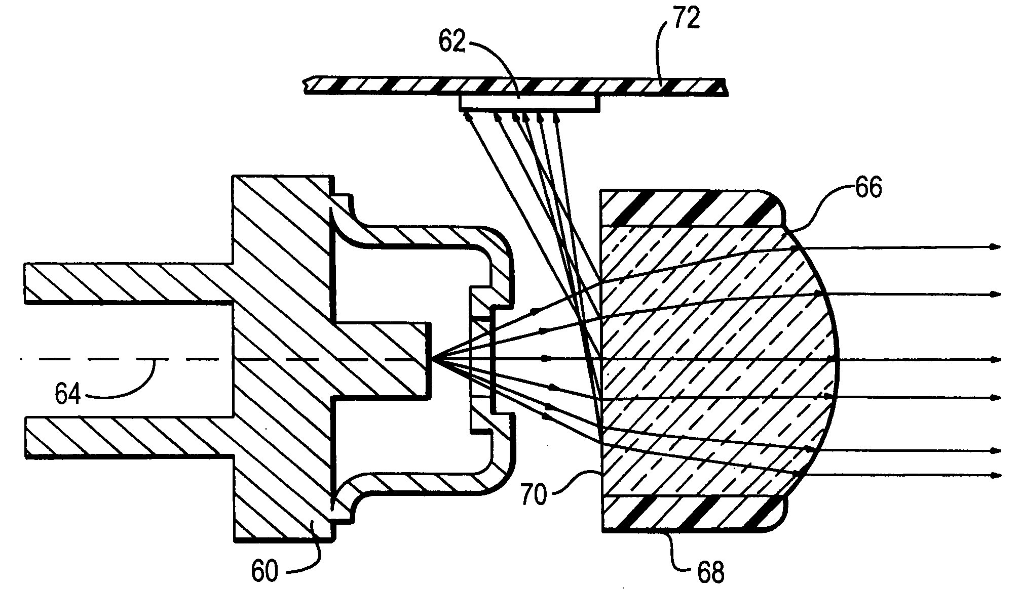
[0009]The direct reception of the portion of the laser beam enhances detection and monitoring of the output power of the laser. Signal reception at the detector is stronger and more consistent than heretofore. In the case of a moving laser beam reader where the laser is employed for reading the symbol, and where the detector is employed in a control circuit for detecting reading laser malfunction, the enhanced signal reception at the detector enables the reading laser to be configured to emit more power to more closely approach established maximum safety standards, because of the increased safety and reliability afforded by the control circuit. More reading laser output power signifies better reading performance, for example, the range of working distances in which the symbol can be read is extended.
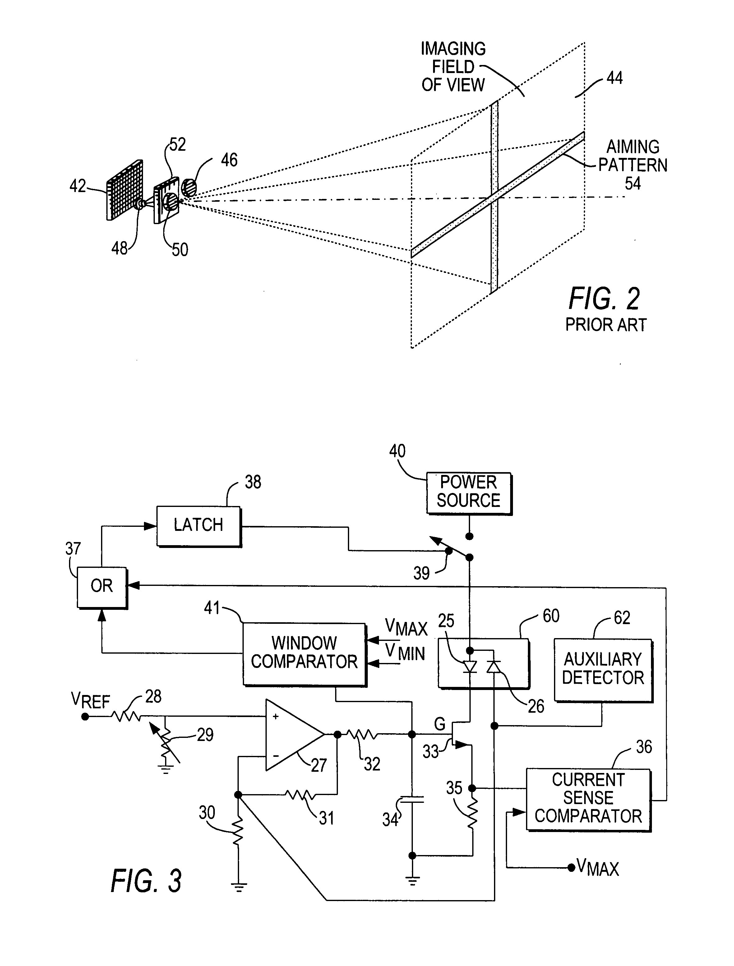
[0010]In the case of an imaging reader where the laser is employed for aiming at the symbol prior to reading, and where the detector is employed in a control circuit for controlling the output power of the aiming laser, the enhanced signal reception at the detector enables the aiming laser to be configured to emit more power to more closely approach established maximum safety standards. More aiming laser output power signifies better reading performance, for example, the visibility of an aiming light pattern projected by the aiming laser is more pronounced.
[0013]In a preferred embodiment, the auxiliary photodiode is mounted, preferably surface-mounted, on a printed circuit board, preferably at a location between the laser and the optical assembly. An enclosure advantageously surrounds the auxiliary photodiode to prevent stray light from entering the auxiliary photodiode.

Problems solved by technology

Although generally satisfactory for its intended purpose, the use of an imaging reader is often frustrating, because an operator cannot tell whether the imager, or the handheld housing in which the imager is mounted, is aimed directly at the target symbol, which can be located anywhere within a range of working distances from the reader.
Also, moving laser beam reader malfunction such as failure of the reading laser must be reliably monitored.

Method used


Image

  • Enhanced monitoring of laser output power in electro-optical readers
  • Enhanced monitoring of laser output power in electro-optical readers
  • Enhanced monitoring of laser output power in electro-optical readers

Examples


Embodiment Construction

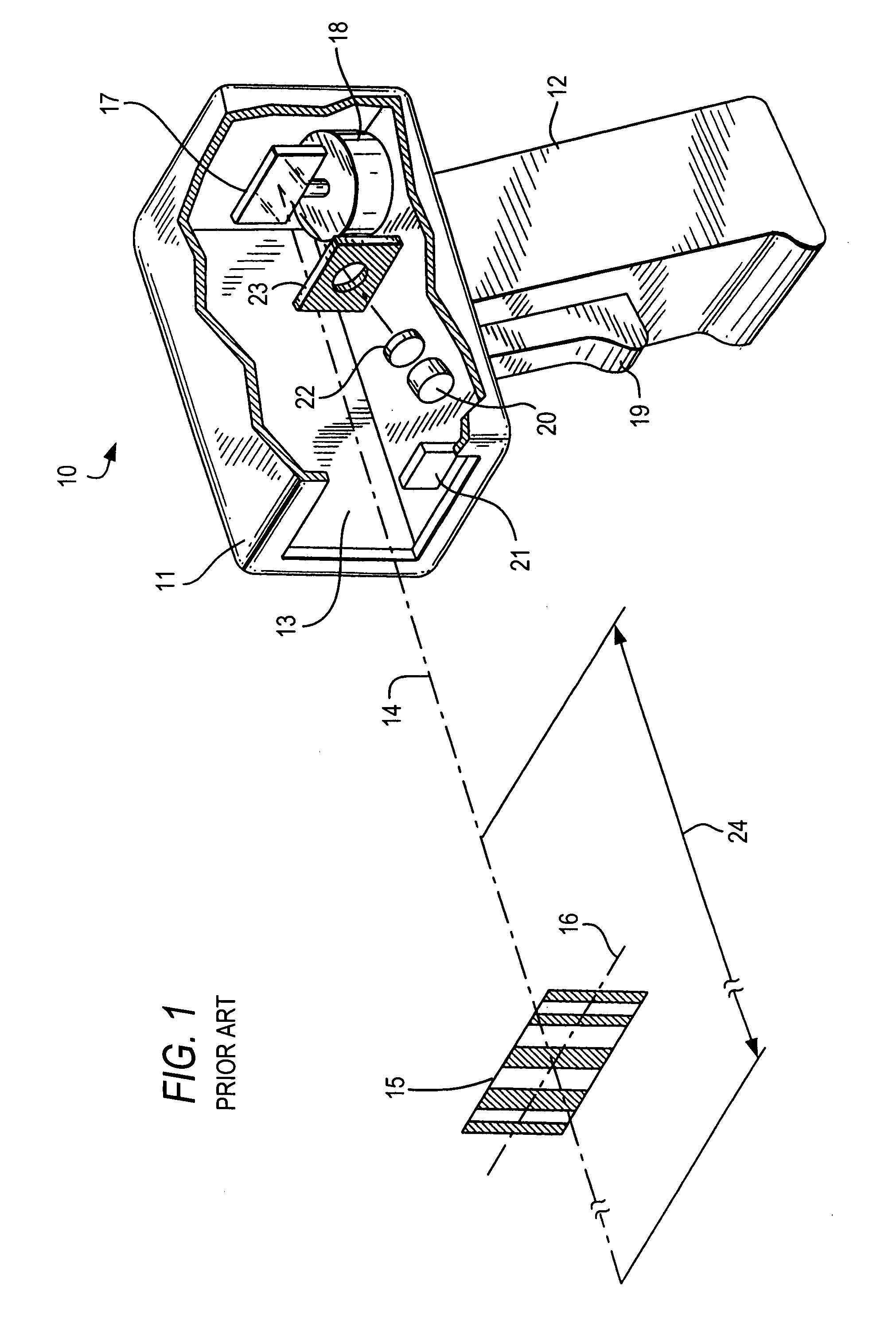
[0021]As used herein, the term “symbol” broadly encompasses not only symbol patterns composed of alternating bars and spaces of various widths as commonly referred to as bar code symbols, but also other one- or two-dimensional graphic patterns, as well as alphanumeric characters. In general, the term “symbol” may apply to any type of pattern or indicia that may be recognized or identified as a representation of variations in light reflectivity at various points of the pattern or indicia. FIG. 1 shows an indicium 15 as one example of a “symbol” to be read. The term “target” broadly encompasses any one- or two-dimensional symbol, as well as any other object to be imaged, including non-symbols, documents, people, etc.

[0022]FIG. 1 depicts a known handheld moving laser beam reader 10 for reading symbols. The reader 10 includes a housing having a barrel portion 11 and a handle 12. Although the drawing depicts a handheld pistol-shaped housing, the invention may also be implemented in other...


PUM


Abstract

Laser power monitoring arrangements interrupt power to a laser used in electro-optical readers upon detection of operating conditions not conforming to preestablished standards. An auxiliary light detector independently monitors the output power of a laser beam, and directly receives a portion of the laser beam reflected from a diffractive optical lens surface of an optical assembly for optically modifying the laser beam, or from a coated or uncoated inclined surface of a split collimating lens of the optical assembly. The split collimating lens may have its lens portions in mutual contact or separated by an air gap.

Description

BACKGROUND OF THE INVENTION[0001]Optical codes or dataforms are patterns made up of image areas having different light-reflective or light-emissive properties, which are typically assembled in accordance with a priori rules. The optical properties and patterns of codes are selected to distinguish them in appearance from the background environments in which they are used. Electro-optical readers identify or extract data from codes and are used in both fixed or portable installations in many diverse environments such as in stores for check-out services, in manufacturing locations for work flow and inventory control, and in transport vehicles for tracking package handling. The code is used as a rapid, generalized means of data entry.[0002]Many conventional readers are designed to read one-dimensional bar code symbols. The bar code symbol is a pattern of variable-width rectangular bars separated by fixed or variable width spaces. The bars and spaces have different light-reflecting chara...

Claims


Application Information

Patent Timeline
IPC IPC(8): G06K7/10
CPCG06K7/10732G06K7/10584
Inventor YU, MINGLIU, RONG
Owner SYMBOL TECH LLC
Learn More