
Touch panel display device

a display device and touch panel technology, applied in the field of touch panel display devices, can solve the problems of power consumption and manufacturing cost are considerably increased, and the conventional device has problems such as high power consumption and manufacturing cost, and achieve the effect of accurate detection of the position touched by the user, high manufacturing cost, and high power consumption

Inactive Publication Date: 2009-06-04
LG DISPLAY CO LTD
View PDF20 Cites 58 Cited by
  • Summary
  • Abstract
  • Description
  • Claims
  • Application Information

AI Technical Summary

Benefits of technology

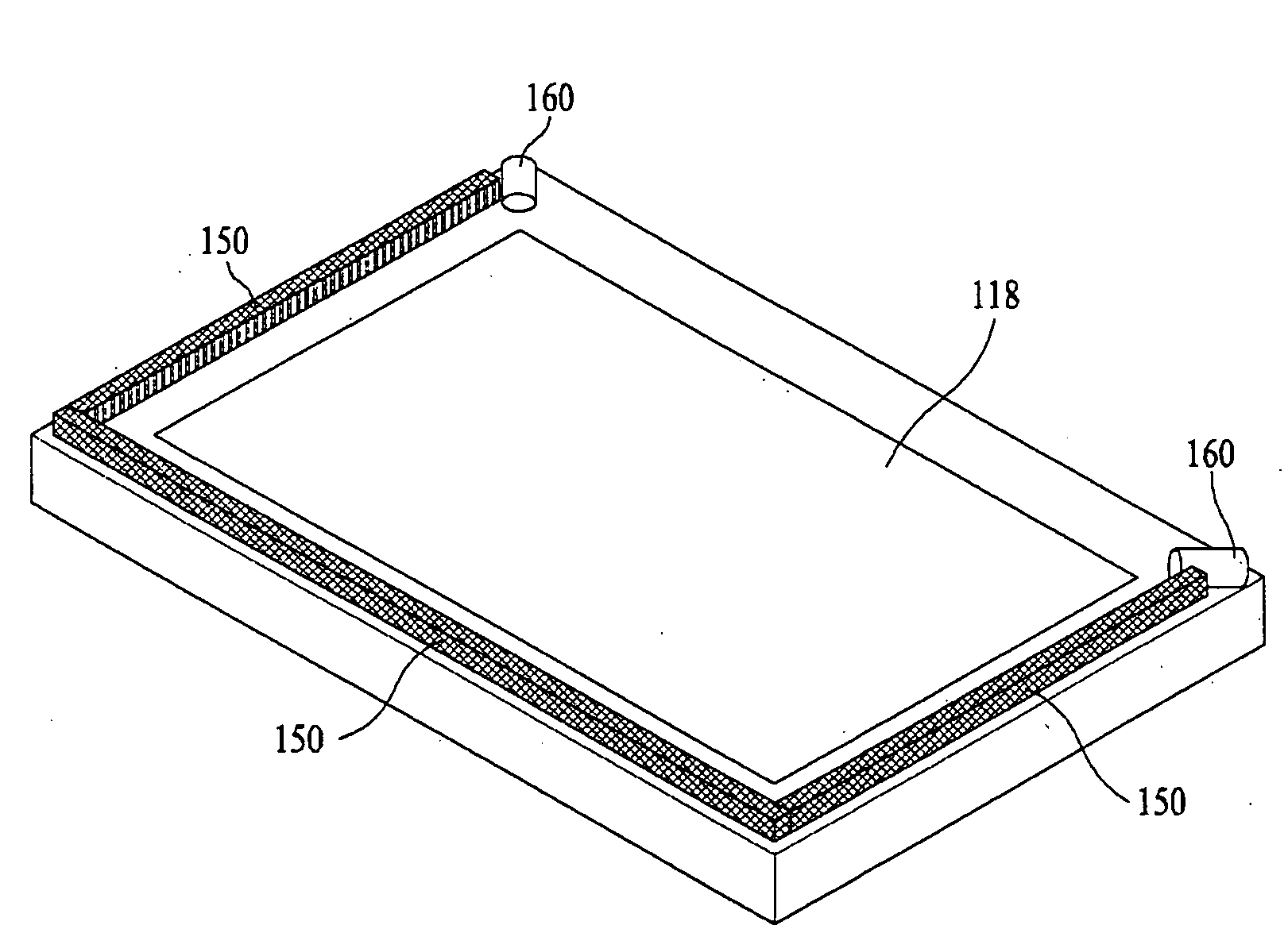
The present invention is a touch panel display device that aims to reduce power consumption and manufacturing costs while improving touch sensitivity. It achieves this by using a liquid crystal panel and a touch sensing part consisting of infrared lamps and image sensors. The infrared lamps are placed on the rear surface of the liquid crystal panel to accurately detect user touch. The device also includes infrared light reflecting tubes mounted with the infrared lamps, which evenly distribute the infrared light on the liquid crystal panel. The image sensors sense the infrared light emitted from the infrared lamps. This design reduces the number of infrared lamps and image sensors, resulting in lower power consumption and manufacturing costs. Additionally, the invention improves touch sensitivity even on large screens.

Problems solved by technology

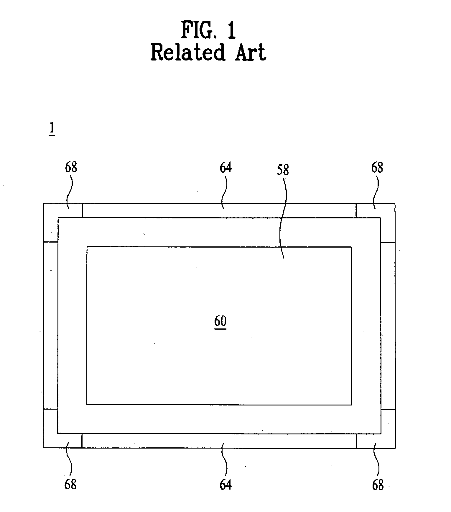
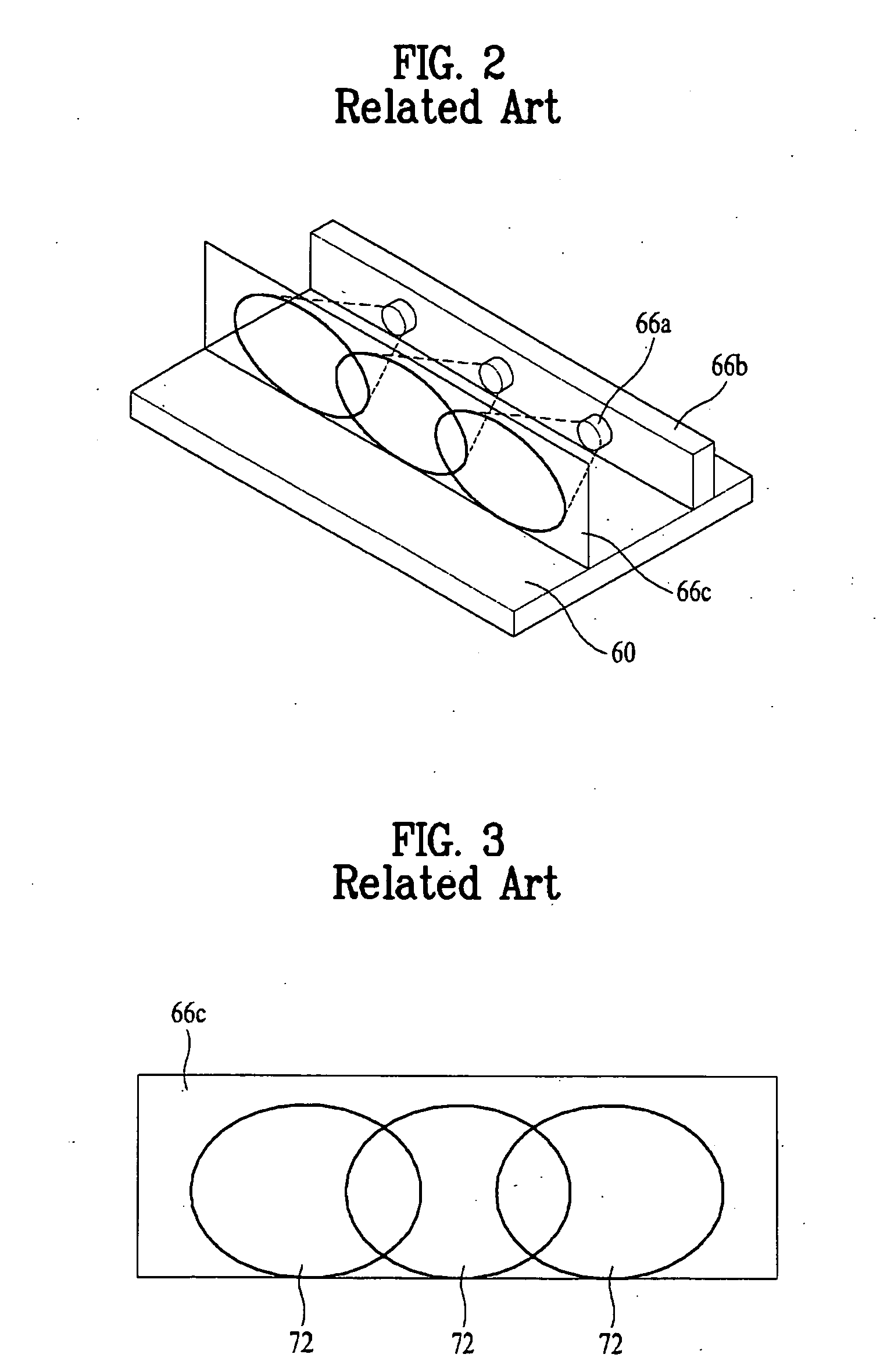
Because the conventional touch panel display device includes a plurality of infrared lamps provided on the rear surface of the liquid crystal panel in order to accurately detect a position touched by a user, the conventional device has problems of high power consumption and high manufacturing costs.
Moreover, because the number of infrared lamps is more increased as the display panel of a larger scale is produced, the power consumption and manufacturing costs are considerably increased.

Method used


Image

  • Touch panel display device
  • Touch panel display device
  • Touch panel display device

Examples


Embodiment Construction

[0047]Reference will now be made in detail to the preferred embodiments of the present invention associated with a touch panel display device, examples of which are illustrated in the accompanying drawings. Wherever possible, the same reference numbers will be used throughout the drawings to refer to the same or like parts.

[0048]FIG. 5 is a sectional view illustrating a touch panel display device according to an exemplary embodiment of the present invention, and FIG. 6 is a perspective view illustrating a touch sensing part of the touch panel display device according to an exemplary embodiment of the present invention.

[0049]Referring to FIGS. 5 and 6, a touch panel display device 100 according to the present invention includes a back light unit, a liquid crystal panel 118 which receives the light supplied from the back light unit and displays an image by regulating light transmittance, and a touch sensing part 130 provided above a liquid crystal display module including the back lig...


PUM


Abstract

A touch panel display device includes a liquid crystal panel to display an image by regulating transmittance of light supplied from a back light unit, and a touch sensing part provided on upper edges of the liquid crystal panel in order to detect a position touched by a user or an object. The touch sensing part includes infrared lamps to generate and emit infrared light, infrared light reflecting tubes mounted with the infrared lamps, and image sensors to sense the infrared light output from the light output regions of the infrared light reflecting tubes. Each of the infrared light reflecting tubes has light output regions and non-output regions evenly formed at a surface facing an upper surface of the liquid crystal panel so that the infrared light emitted from the infrared lamps is evenly irradiated on the upper surface of the liquid crystal panel.

Description

[0001]This application claims the benefit of Korean Patent Application No. 10-2007-0124168 filed on Dec. 3, 2008, which is hereby incorporated by reference as if fully set forth herein.BACKGROUND OF THE INVENTION[0002]1. Field of the Invention[0003]The present invention relates to a touch panel display device, and more particularly, to a touch panel display device capable of decreasing power consumption and manufacturing costs by reducing the number of image sensors and infrared light emitting diodes, and capable of improving touch sensitivity even when a screen has a large scale.[0004]2. Discussion of the Related Art[0005]With the wide use of computers for data processing, users increasingly need to input more data to data processors, such as workstations, personal computers, etc., or need data processing (e.g., data conversion) using data processors. Diverse application programs can be applied to the recent developed data processors, and complex data processing can be achieved by ...

Claims


Application Information

Patent Timeline
Patent Type & Authority Applications(United States)
IPC IPC(8): G06F3/042G06F3/041
CPCG02F1/13338G06F3/0421G06F3/0412G02F2203/11G06F3/0304
Inventor SOHN, MIN HOCHOI, JONG SEONGJANG, HYUNG UKLEE, SANG RAEBAE, SANG HYUCKYU, BYUNG CHUN
Owner LG DISPLAY CO LTD
Learn More