
Multiplex method of VLAN switching tunnel and VLAN switching system

a virtual local area network and multi-mode switching technology, applied in the field ofethernet technology, can solve the problems of low utilization of vs tunnels, difficult to apply large-scale networks, and scalability of methods, and achieve the effects of reducing network deployment costs, operation maintenance costs, and simple functions

Inactive Publication Date: 2009-06-04
HUAWEI TECH CO LTD
View PDF5 Cites 88 Cited by
  • Summary
  • Abstract
  • Description
  • Claims
  • Application Information

AI Technical Summary

Benefits of technology

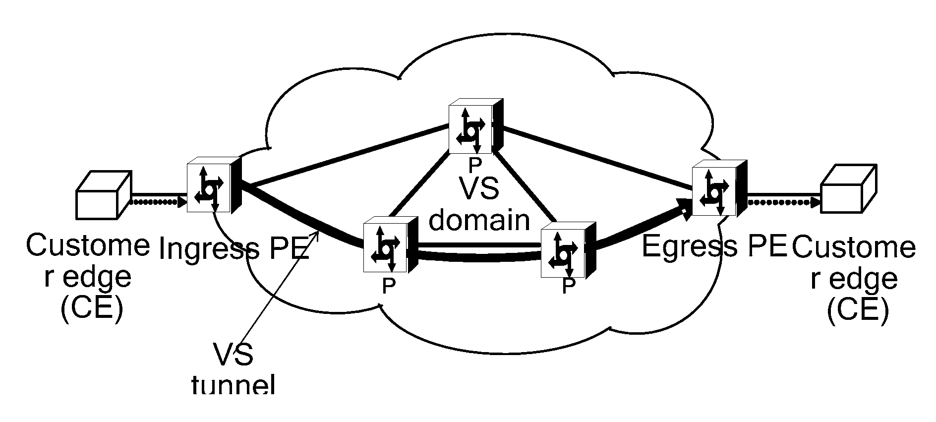
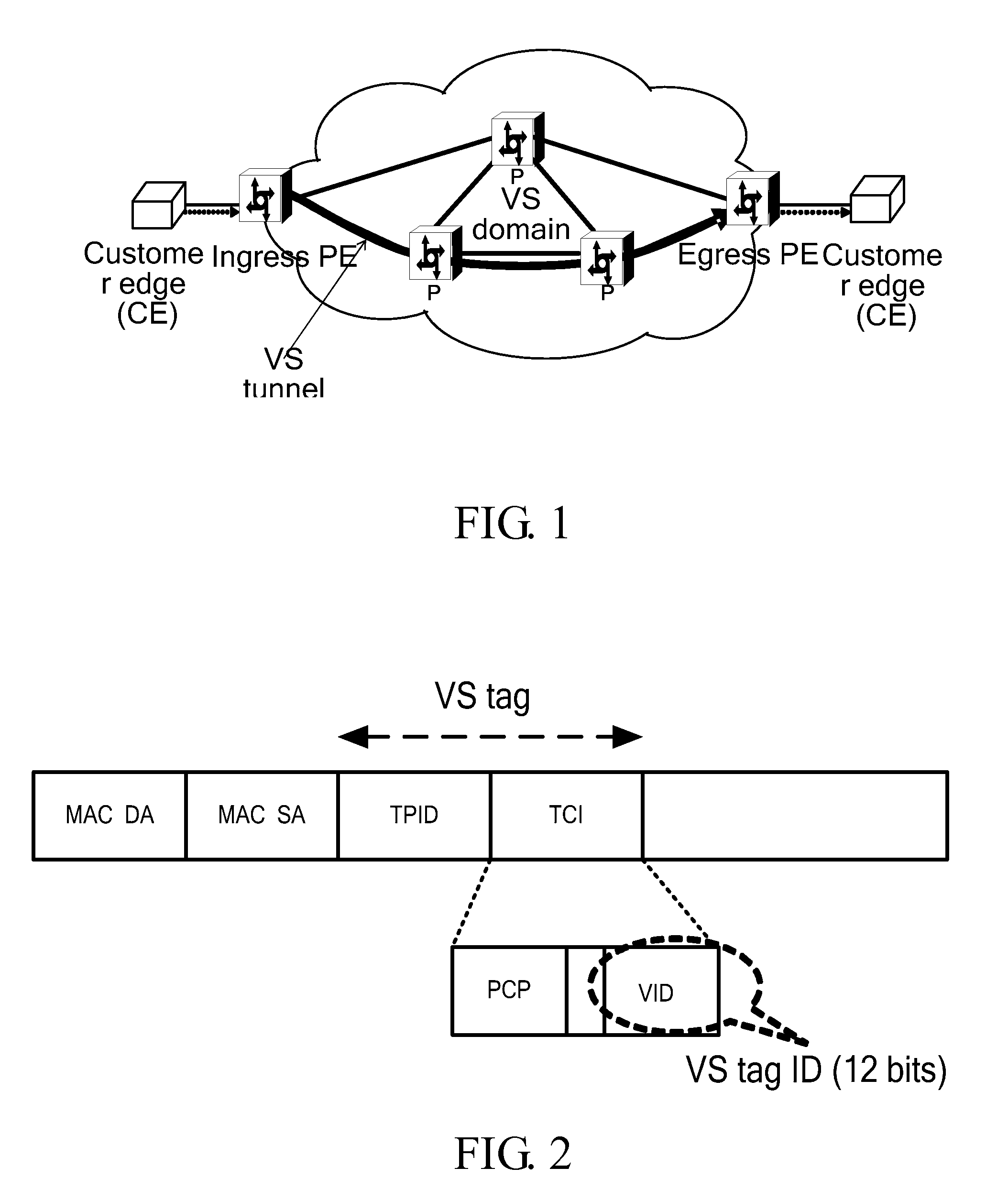
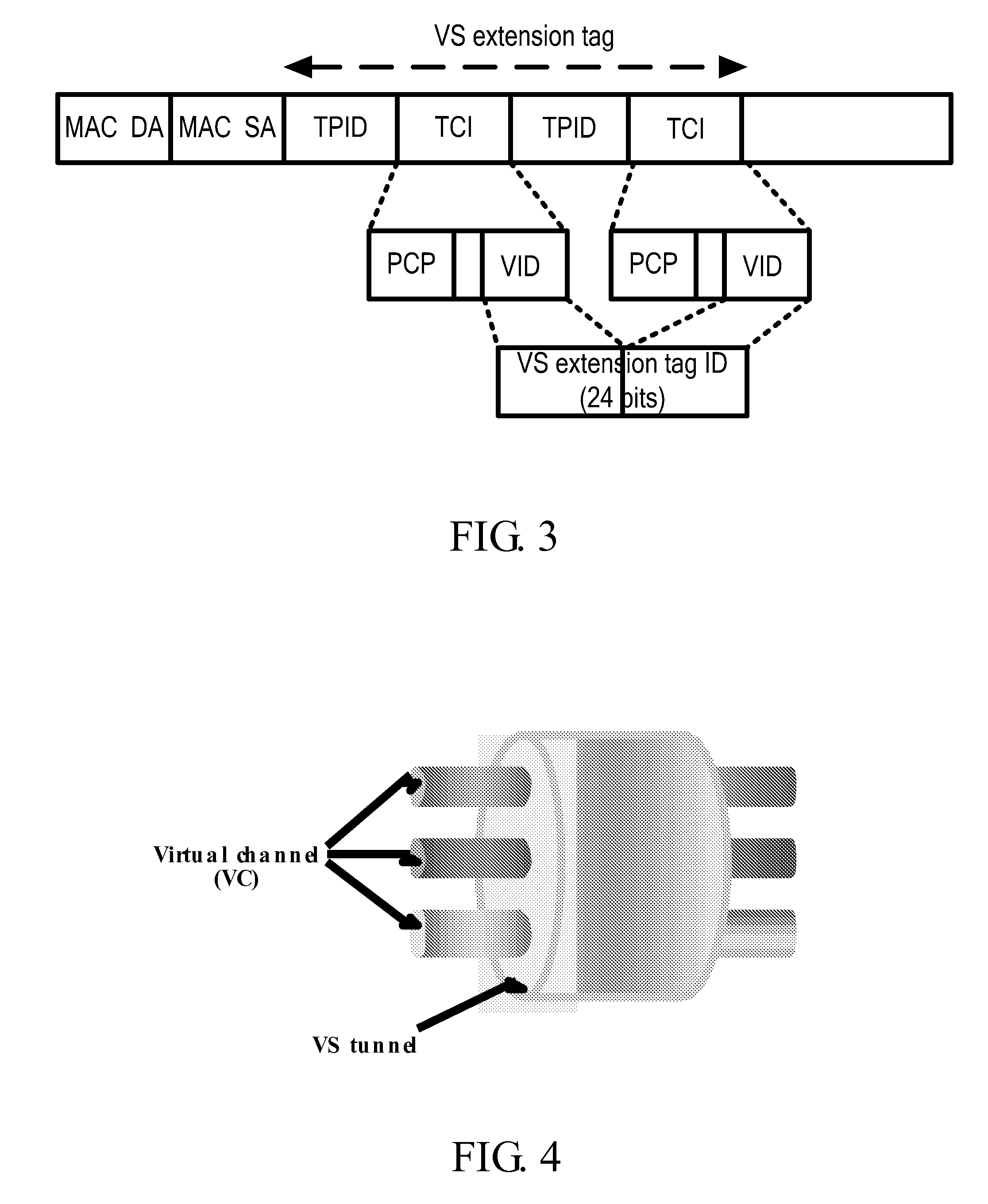
[0038](1) With the embodiments of the present invention, the ingress edge node of the VS tunnel maps a received customer data unit onto one VC borne by the VS tunnel, and encapsulates it into a VS tunnel Ethernet frame, wherein the VS tunnel Ethernet frame includes a VS tag, a VC tag, and the customer data unit. The VC tag identifies different VCs borne by the VS tunnel. The intermediate node of the VS tunnel switches the VS tunnel Ethernet frame according to the VS tag, and transports the customer data unit and the VC tag transparently in the VS tunnel. The egress edge node of the VS tunnel terminates the VS tunnel and the VC, recovers the customer data unit, and forwards data according to the VC tag. In this way, an explicit multiplex of the VS tunnel is realized and the utilization of the VS tunnel is improved by bearing multiple VCs on one VS tunnel in the embodiments of the present invention, which greatly reduces the number of constructed VS tunnels and alleviates the scalability problem resulted from 12-bit VS.
[0040](3) In the embodiments of the present invention, only edge nodes in the VS domain need to process the VC, while the intermediate nodes in the VS domain have a simple function and only needs to perform a VS switching on few VS tunnels, which definitely reduces the network deployment cost as well as operation maintenance cost.

Problems solved by technology

Since the above method uses one layer of VLAN tags as the VS tag for switching and the VID is limited to 12 bits, the number of VS tunnels borne on each link cannot break through 4096 (i.e., 212), and thus the method has scalability problem and is difficult to be applied in large scale networks.
Being a non-routine practice, the method currently has not been well accepted in the industry.
The existing VS technology does not provide an explicit multiplex method of the VS tunnel, in which one VS tunnel can only bear one VS connection, and a VS tunnel needs to be established for each VS connection respectively, so that the utilization of the VS tunnel is low, and a large number of tunnels need to be constructed, which causes the scalability problem of 12-bit VS to be more serious.
On the other hand, an implicit multiplex in which multiple services are connected to one VS tunnel by service application inevitably causes too tight coupling between the service flow and the VS bearer technology and complicated service processing, which is disadvantageous in the development of service.

Method used


Image

  • Multiplex method of VLAN switching tunnel and VLAN switching system
  • Multiplex method of VLAN switching tunnel and VLAN switching system
  • Multiplex method of VLAN switching tunnel and VLAN switching system

Examples


first embodiment

[0064]In a first embodiment, the VS tunnel Ethernet frame is encapsulated using a QinQ Ethernet frame defined by the IEEE 802.1ad. Referring to FIG. 6, the VS tunnel employs the QinQ Ethernet frame defined by the IEEE 802.1ad in encapsulating, an S-TAG in an external layer is used as the VS tag for the switching of the VS tunnel, and a C-TAG in an internal layer is used as the VC tag for identifying the VC borne by the VS tunnel. In this situation, the length of a VCI is equal to that of one VID, i.e., 12 bits.

[0065]Since the QinQ Ethernet frame encapsulation has been generally accepted, the first embodiment has wide applications.

second embodiment

[0066]In a second embodiment, the VS tunnel Ethernet frame is encapsulated using an 802.1ah Ethernet frame.

[0067]Referring to FIG. 7, the VS tunnel Ethernet frame is encapsulated using the Ethernet frame defined by the IEEE 802.1ah, a backbone VLAN tag (B-TAG) in the 802.1ah Ethernet frame encapsulation is used as the VS tag for the switching of the VS tunnel, and a service instance tag (I-TAG) is used as the VC tag. In this situation, the length of a VCI is equal to that of a service instance ID (I-SID) which is 24 bits.

[0068]Therefore, with the second embodiment, the VC address space is sufficient.

third embodiment

[0069]In a third embodiment, the encapsulation is performed by using a V-TAG / S-TAG in an Ethernet frame header as the VS tag, and an MPLS label as a VC tag.

[0070]Referring to FIG. 8, the VS tunnel employs the V-TAG in the Ethernet frame structure defined by the IEEE 802.1q or the S-TAG in the QinQ Ethernet frame defined by the IEEE 802.1ad as the VS tunnel, and employs the MPLS label as the VC tag. In this situation, the length of a VCI is equal to that of the MPLS label which is 20 bits.

[0071]With the third embodiment, the following advantages may be achieved.

[0072]a. The Ethernet and MPLS encapsulation are mature enough.

[0073]b. The length of the MPLS label guarantees a sufficient VC address space.

[0074]c. With this embodiment of the present invention, an intermediate node in the VS domain transports the VC tag transparently, and thus the MPLS forwarding capability is not required.

[0075]d. The VC tag, a pseudo wire (PW) label defined by the PWE3 and VPLS, and an internal layer tag...


PUM


Abstract

A multiplex method of a virtual local area network (VLAN) switching (VS) tunnel includes the following steps. An ingress edge node of the VS tunnel maps a received customer data unit onto one virtual channel (VC) borne by the VS tunnel, and encapsulates the customer data unit into a VS tunnel Ethernet frame including a VS tag, a VC tag, and the customer data unit. The VC tag identifies the different VCs borne by the VS tunnel. An intermediate node of the VS tunnel switches the VS tunnel Ethernet frame according to the VS tag, and transports the customer data unit and the VC tag transparently in the VS tunnel. An egress edge node of the VS tunnel terminates the VS tunnel and the VC, recovers the customer data unit, and forwards the data according to the VC tag.

Description

CROSS-REFERENCE TO RELATED APPLICATIONS[0001]This application is a continuation of International Application No. PCT / CN2007 / 002841 filed on Sep. 28, 2007, which claims priority to Chinese Patent Application No. 200610140663.9, filed on Sep. 29, 2006, both of which are hereby incorporated by reference in their entireties.BACKGROUND OF THE INVENTION[0002]1. Field of the Technology[0003]The present invention relates to an Ethernet technology, and more particularly to a multiplex method of a virtual local area network (VLAN) switching (VS) tunnel and a VS system.[0004]2. Background of the Invention[0005]Ethernet technology becomes one of the main technologies for building a metropolitan area network in the future and is widely applied at each level of the broadband metropolitan area network for its concise and sound openness, significant cost advantage, wide applicability and recognition.[0006]Meanwhile, the industry has clearly realized that problems in five aspects of scalability, rel...

Claims


Application Information

Patent Timeline
Patent Type & Authority Applications(United States)
IPC IPC(8): H04L12/56
CPCH04L12/4633H04L12/4662H04L12/4658H04L12/4654
Inventor FAN, LINGYUAN
Owner HUAWEI TECH CO LTD
Learn More