
Road vehicle control method

a technology for controlling vehicles and vehicles, applied in the field of road vehicle control methods, can solve the problems of driving safety reduction, overestimation of driving abilities, and incorrect estimation of driving abilities by drivers, and achieve the effect of easy and cost-effective implementation

Inactive Publication Date: 2009-06-04
FAB ITAL MAGNETI MARELLI SPA
View PDF11 Cites 36 Cited by
  • Summary
  • Abstract
  • Description
  • Claims
  • Application Information

AI Technical Summary

Benefits of technology

[0009]It is the object of the present invention to provide a road vehicle control method, which control method is free from the above-described drawbacks and, specifically, is easy and cost-effective to implement.

Problems solved by technology

However, it is not uncommon for the driver to incorrectly estimate, and specifically overestimate, his or her driving abilities; consequently, the selection made by the driver in relation to the dynamic behaviour of the car may reflect a mere aspiration of the driver and not the real driving ability of the driver him or herself.
In these situations, the selection made by the driver in relation to the dynamic behaviour of the car is translated into a reduction of driving safety, because the driver is driving a car which inappropriately responds to the real driving abilities of the driver him or herself.
Such a situation may easily occur in the case of a young, newly licensed driver who is often led to overestimate his or her driving abilities and to underestimate the dangers of the road.
Such a draft law has the unquestionable advantage of not allowing newly licensed drivers to drive cars with excessively high performances with respect to their driving abilities, but on the other hand also has several disadvantages, because it obliges newly licensed drivers to drive lower segment cars only because they alone have a weight / power ratio lower than the maximum threshold established by law.

Method used


Image

  • Road vehicle control method
  • Road vehicle control method

Examples


Embodiment Construction

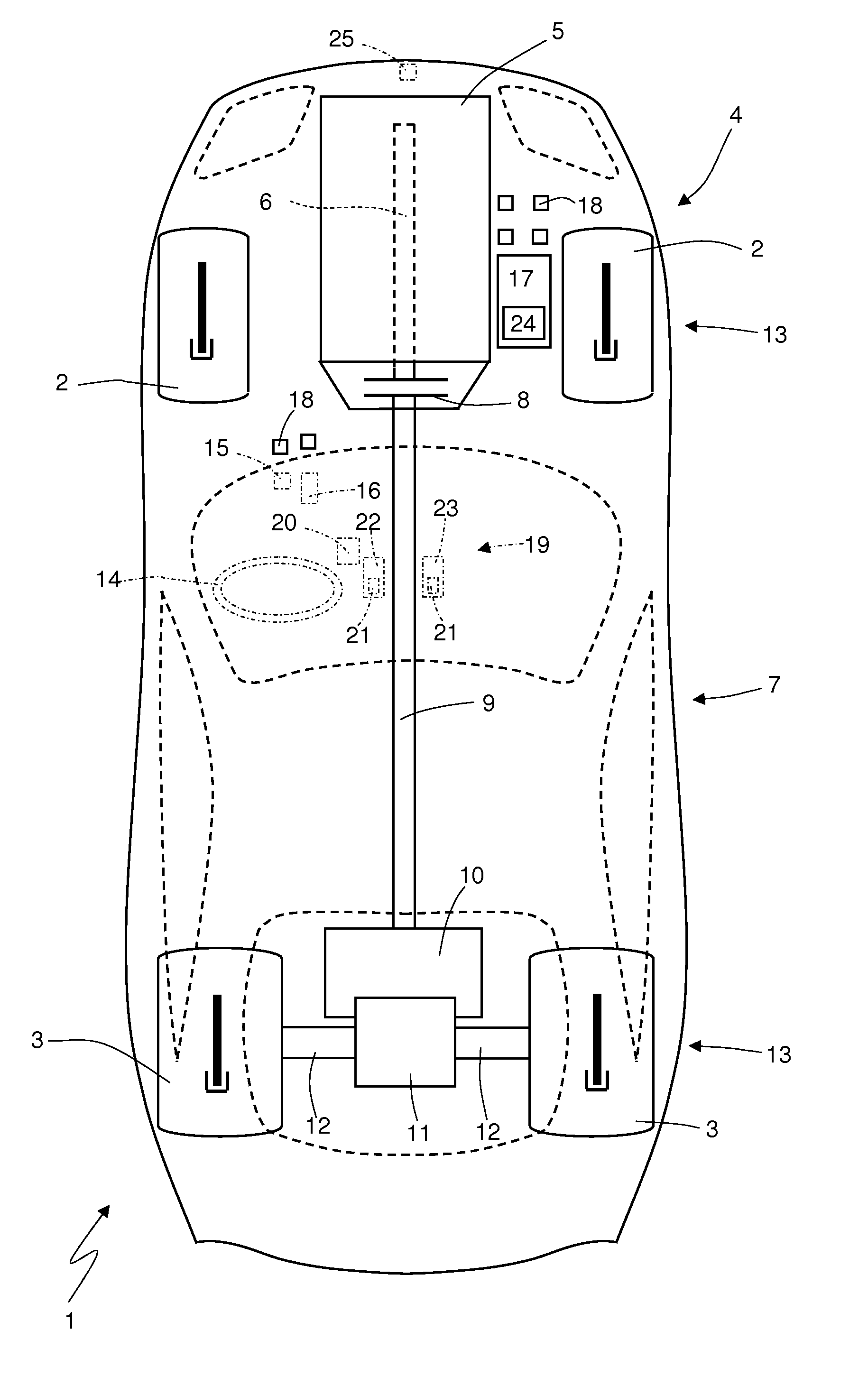
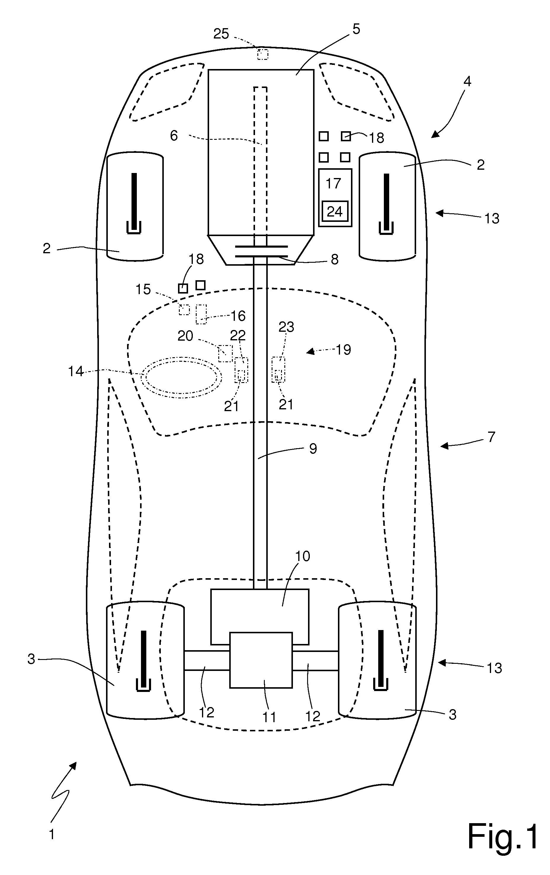
[0012]In FIG. 1, numeral 1 indicates as a whole a car provided with two front wheels 2 and two rear driving wheels 3 which receive the torque from a power system 4.

[0013]The power system 4 comprises an internal combustion heat engine 5, which is arranged in a frontal position and is provided with a drive shaft 6, and a servo controlled transmission 7, which transmits the torque generated by the internal combustion engine 5 to the rear driving wheels 3 and comprises a servo controlled clutch 8 accommodated in a cover integral with the internal combustion engine 5.

[0014]The clutch 8 is interposed between the drive shaft 6 and a propeller shaft 9 ending in a servo controlled mechanical gearbox 10, which is arranged in a rear position and is provided with a primary shaft connected to the propeller shaft 9 and a secondary shaft connected to a differential 11 from which a pair of axle shafts 12 integral with the rear driving wheels 3 departs. The car 1 further comprises a braking system 1...


PUM


Abstract

A control method of a road vehicle; the control method includes the steps of: detecting the position of an accelerator control which is displaced along a predetermined stroke; using the position of the accelerator control to control the generation of a torque generated by the engine of the road vehicle so that the torque is generated according to the position of the accelerator control; detecting the current driver's ability by means of a driving ability recognition device; and limiting the generation of torque according to the current driver's ability.

Description

CROSS REFERENCE TO RELATED APPLICATION[0001]This application claims the priority of European Patent Application No: 07425675.1, filed on Oct. 29, 2007, the subject matter of which is incorporated herein by reference.TECHNICAL FIELD[0002]The present invention relates to a road vehicle control method.[0003]The present invention is advantageously applied to a car, to which explicit reference will be made in the following description without therefore loosing in generality.BACKGROUND ART[0004]In order to attempt to make driving safer, modern cars are equipped with a series of electric driving assistance devices; for example, such electronic driving assistance devices may be the ABS (Anti Block System—to prevent wheels locking while braking), the ESP (Electronic Stability Program—to control vehicle stability), the ASP (Anti Skid Program—to prevent the driving wheels from skidding), and the electronic suspension control (to vary the mechanical response of the suspensions to external stres...

Claims


Application Information

Patent Timeline
Patent Type & Authority Applications(United States)
IPC IPC(8): G06F19/00G01S1/00B60W40/08G01S19/36
CPCB60Q1/50B60W40/09B60W2040/0818B60W2550/402B60W2550/14B60W2550/143B60W2550/22B60W2540/28B60W2540/043B60W2552/20B60W2552/00B60W2555/60B60W2556/50B60W2552/30B60Q1/544
Inventor GAVIANI, GIOVANNI MARIANESCI, WALTERDALLA, ROBERTO
Owner FAB ITAL MAGNETI MARELLI SPA
Learn More