Traveling Direction Measuring Apparatus and Traveling Direction Measuring Method

a technology of measuring apparatus and measuring method, which is applied in the direction of distance measurement, navigation instruments, instruments, etc., can solve the problems of reducing accuracy, affecting positioning accuracy, and requiring considerable cost and time, and achieves high positioning accuracy

Inactive Publication Date: 2009-06-04
ASAHI KASEI ELECTRONICS CO LTD
View PDF3 Cites 43 Cited by
  • Summary
  • Abstract
  • Description
  • Claims
  • Application Information

AI Technical Summary

Benefits of technology

[0027]The present invention provides the traveling direction measuring apparatus and traveling direction measuring method usable as the pedestrian navigation system in locations where it is difficult to obtain high positioning accuracy such as inside buildings or around multistory building

Problems solved by technology

The positioning utilizing GPS, however, has a problem of hindering the positioning or decreasing accuracy in locations where the GPS signals are very weak as inside buildings or where the sufficient number of supplementary satellites cannot be secured as around buildings.
Any of these indoor positioning systems, however, require developing an infrastructure, which demands considerable cost and time.
However, the apparatuses disclosed in the foregoing Patent Documents 1 t

Method used


Image

  • Traveling Direction Measuring Apparatus and Traveling Direction Measuring Method
  • Traveling Direction Measuring Apparatus and Traveling Direction Measuring Method
  • Traveling Direction Measuring Apparatus and Traveling Direction Measuring Method

Examples


Embodiment Construction

[0041]The best mode for carrying out the invention will now be described with reference to the accompanying drawings to explain the present invention in more detail.

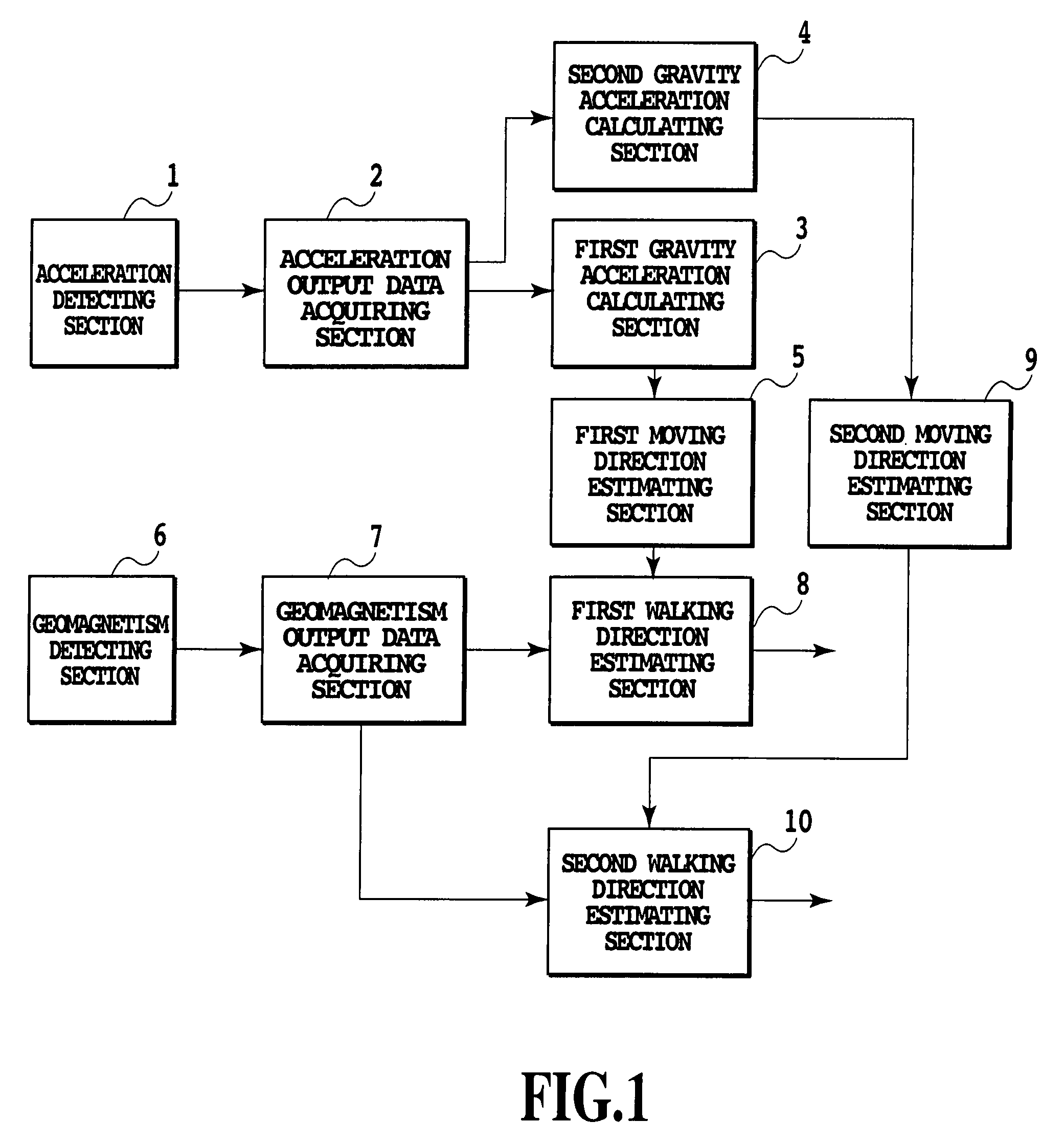
[0042]FIG. 1 is a block diagram showing a configuration of an embodiment of a traveling direction measuring apparatus in accordance with the present invention. In FIG. 1, the reference numeral 1 designates a 3-axes acceleration detecting section, the reference numeral 2 designates an acceleration data acquiring section, the reference numeral 3 designates a first gravity acceleration calculating section, the reference numeral 4 designates a second gravity acceleration calculating section, the reference numeral 5 designates a first moving direction estimating section, the reference numeral 6 designates a 3-axes geomagnetism detecting section, the reference numeral 7 designates a geomagnetism data acquiring section, the reference numeral 8 designates a first walking direction estimating section, the reference numeral 9 desi...


PUM


Abstract

The present invention relates to a traveling direction measuring apparatus usable as a pedestrian navigation system in locations where it is difficult to obtain high positioning accuracy such as inside buildings or around multistory buildings where a GPS cannot be used. An acceleration detecting section (1) detects 3-axes acceleration of the traveling direction measuring apparatus, which varies with the walking of the pedestrian. An acceleration data acquiring section (2) obtains 3-axes acceleration data repeatedly by the number of prescribed times or more, said 3-axes acceleration data varies with the walking of the pedestrian. A first gravity acceleration calculating section (3) calculates, when the pedestrian is walking with holding the traveling direction measuring apparatus in a generally fixed attitude, gravity acceleration by averaging acceleration data sets during several steps obtained by the acceleration data acquiring section (2). A first moving direction estimating section (4) estimates the moving direction of the pedestrian from frequency components corresponding to the duration of one step of the acceleration data sets projected on a plane perpendicular to the gravity acceleration calculated by the first gravity acceleration calculating section (3).

Description

TECHNICAL FIELD[0001]The present invention relates to a traveling direction measuring apparatus and traveling direction measuring method, and more particularly to a traveling direction measuring apparatus and traveling direction measuring method usable as a pedestrian navigation system in a mobile terminal including a geomagnetic sensor and acceleration sensor in locations where it is difficult to obtain high positioning accuracy such as inside buildings or around multistory buildings where GPS (Global Positioning system) cannot be used.BACKGROUND ART[0002]Recently, small-sized mobile terminals with a GPS function, typified by mobile phones, have been extensively developed. These mobile terminals have such applications as navigating pedestrians in collaboration with the GPS system, the distribution of maps via a mobile phone network, and a display application.[0003]The positioning utilizing GPS, however, has a problem of hindering the positioning or decreasing accuracy in locations ...

Claims


Application Information

Patent Timeline
IPC IPC(8): G01C21/10G01C21/00G01P13/02
CPCA61B5/1112A61B5/1126A61B2562/0219G08G1/005G01C22/006G01P13/02G01C21/20
Inventor KITAMURA, TORUYAMASHITA, MASAYA
Owner ASAHI KASEI ELECTRONICS CO LTD
Why Eureka
Try Eureka