
Network with distributed shared memory

a technology of shared memory and network, applied in the direction of memory addressing/allocation/relocation, digital computers, instruments, etc., can solve the problems of significant architectural changes, hardware requirements that limit the ability to share and/or increase memory capacity, and the difficulty of sharing computer memory (ram)

Inactive Publication Date: 2009-06-04
DELL PROD LP
View PDF13 Cites 113 Cited by
  • Summary
  • Abstract
  • Description
  • Claims
  • Application Information

AI Technical Summary

Problems solved by technology

The sharing of computer memory (RAM) has proved more difficult in many respects.
Accordingly, hardware requirements often impose limitations on the ability to share and / or increase memory capacity.
Although various solutions have been proposed, the solutions commonly involve significant architectural changes and often require specialized software to take advantage of the changed memory architecture.

Method used


Image

  • Network with distributed shared memory
  • Network with distributed shared memory
  • Network with distributed shared memory

Examples


Embodiment Construction

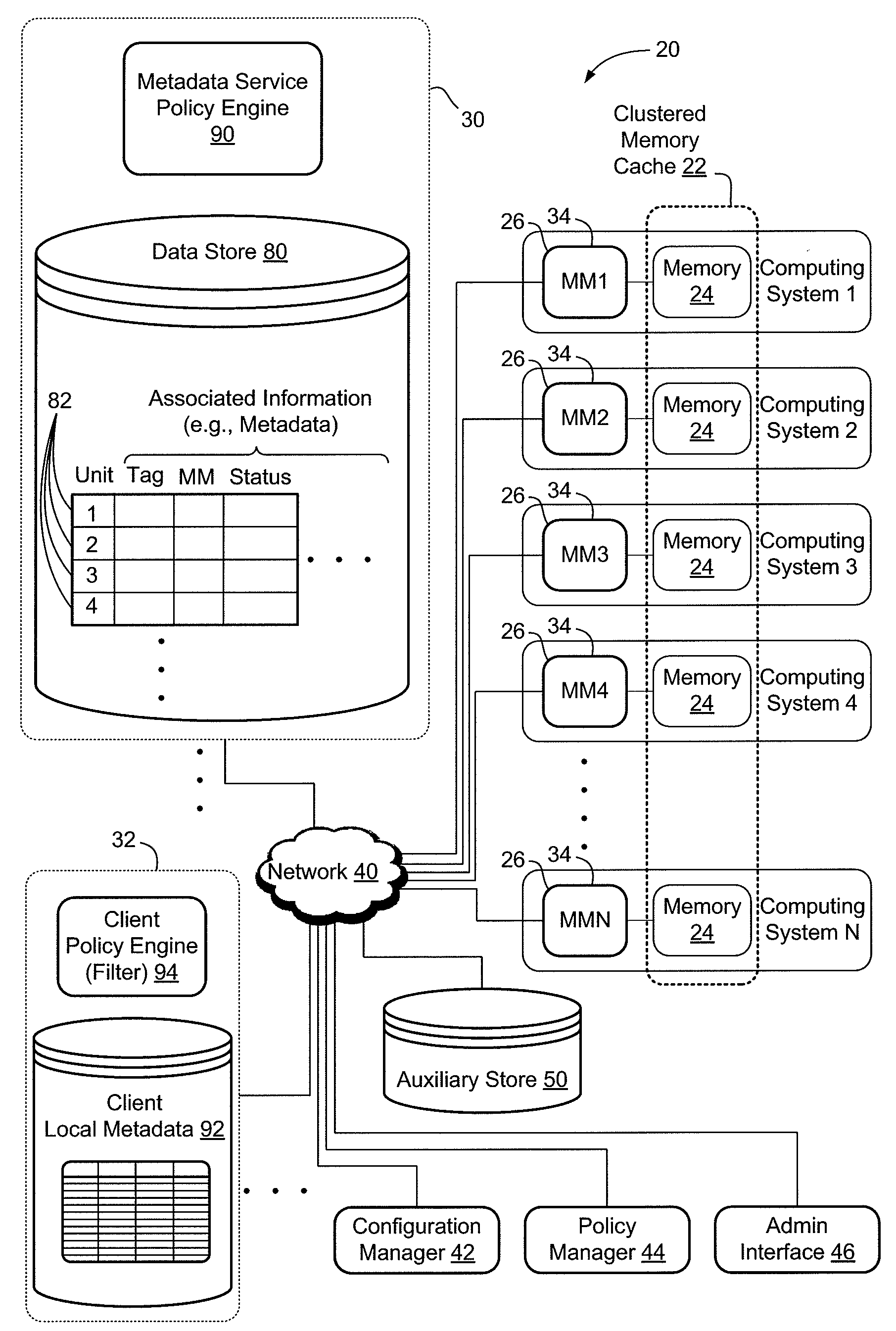
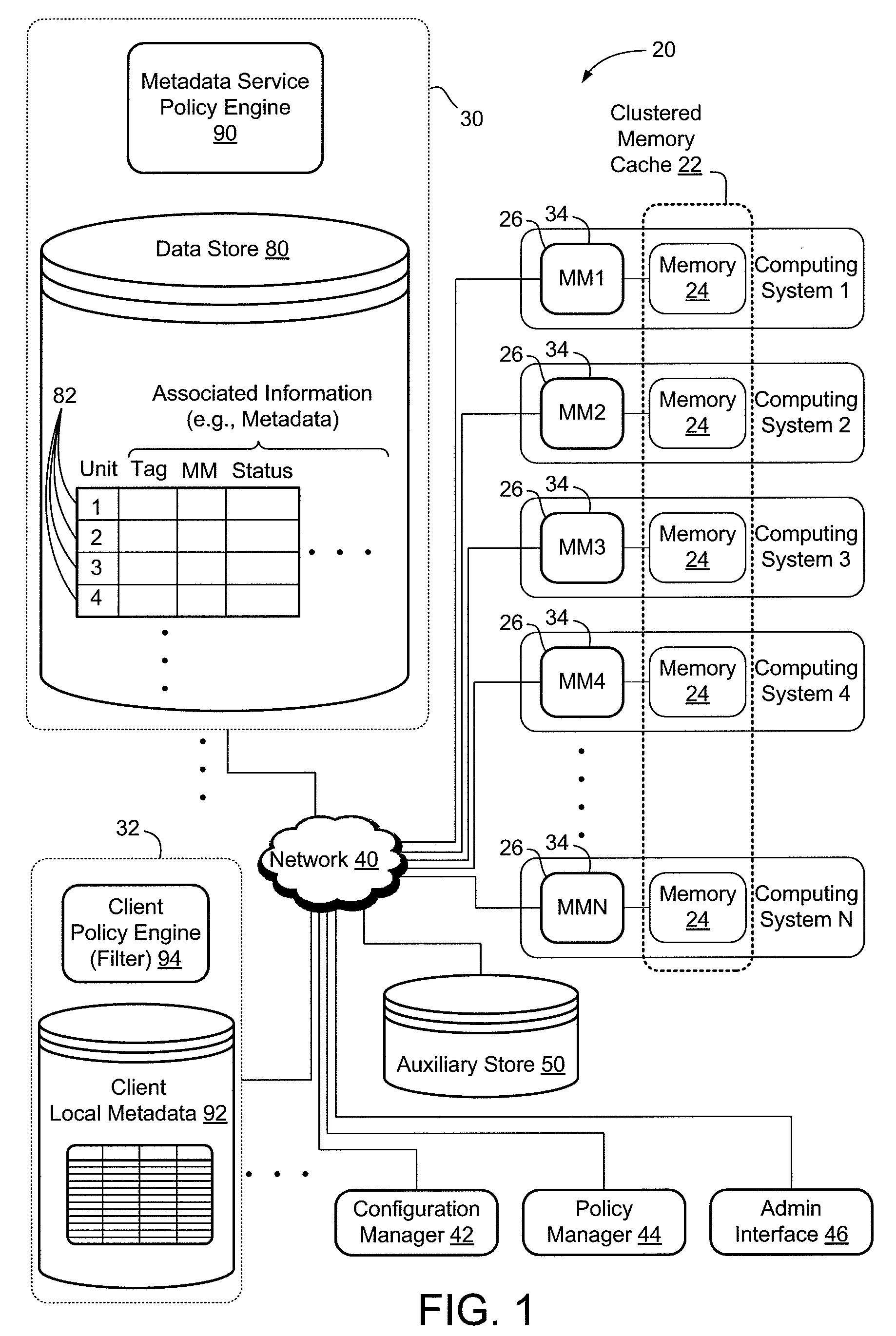
[0010]FIG. 1 depicts a computer network 20 with distributed memory. The memory resource and supporting systems may be configured in a variety of different ways and for different applications. Page caching is one example of a setting where numerous advantages can be obtained. Accordingly, the distributed memory resource in the example of FIG. 1, and in other examples discussed herein, includes a clustered memory cache 22. Referring specifically to FIG. 1, clustered memory cache 22 is aggregated from and comprised of physical memory locations 24 on a plurality of physically distinct computing systems 26 (individually designated as Computing System 1, Computing System 2, etc.) Computer network 20 also includes a metadata service 30, a plurality of clients 32 (only one client is shown in the figure), and a plurality of local memory managers 34 (individually designated as MM1, MM2, etc.). Each of the local memory managers is local to and associated with a different portion of clustered m...


PUM


Abstract

A computer network with distributed shared memory, including a clustered memory cache aggregated from and comprised of physical memory locations on a plurality of physically distinct computing systems. The clustered memory cache is accessible by a plurality of clients on the computer network and is configured to perform page caching of data items accessed by the clients. The network also includes a policy engine operatively coupled with the clustered memory cache, where the policy engine is configured to control where data items are cached in the clustered memory cache.

Description

CROSS-REFERENCE TO RELATED APPLICATION[0001]The present application claims priority to U.S. Provisional Patent Application Ser. No. 60 / 986,377, entitled RESOURCE CLUSTERING IN ENTERPRISE NETWORKS filed Nov. 8, 2007, the disclosure of which is hereby incorporated by reference.BACKGROUND[0002]The present disclosure relates to sharing memory resources in computer networks. A broad class of computing innovation involves the combining of computing resources to provide various benefits. For example, a wide variety of technologies are used to allow distributed storage devices (e.g., hard drives) to be combined and logically accessed as a unified, shared storage resource. Processing resources have also been combined and / or divided, for example, in multiprocessor and parallel processing systems, and in virtual machine environments.[0003]The sharing of computer memory (RAM) has proved more difficult in many respects. Typically, discrete memory chips are combined by tightly coupling the chips ...

Claims


Application Information

Patent Timeline
IPC IPC(8): G06F15/167G06F15/173G06F12/08
CPCG06F12/0813G06F15/167G06F12/084G06F12/0817
Inventor GROSS, JASON P.PANDIT, RANJIT B.COOK, CLIVE G.MATSON, THOMAS H.
Owner DELL PROD LP
Learn More