Loading station

a technology for loading stations and loading hoppers, applied in the field of loading stations, can solve the problems of complex and/or expensive construction of loading stations, unsatisfactory handling, etc., and achieve the effect of simple structure and convenient operation

Active Publication Date: 2009-06-11
LIEBHERR VERZAHNTECHNIK GMBH
View PDF5 Cites 21 Cited by
  • Summary
  • Abstract
  • Description
  • Claims
  • Application Information

AI Technical Summary

Benefits of technology

[0008]It is therefore the object of the present invention to provide a loading station which has a simp...

Problems solved by technology

However, these loading stations are complex and/or...

Method used


Image

  • Loading station
  • Loading station
  • Loading station

Examples


Embodiment Construction

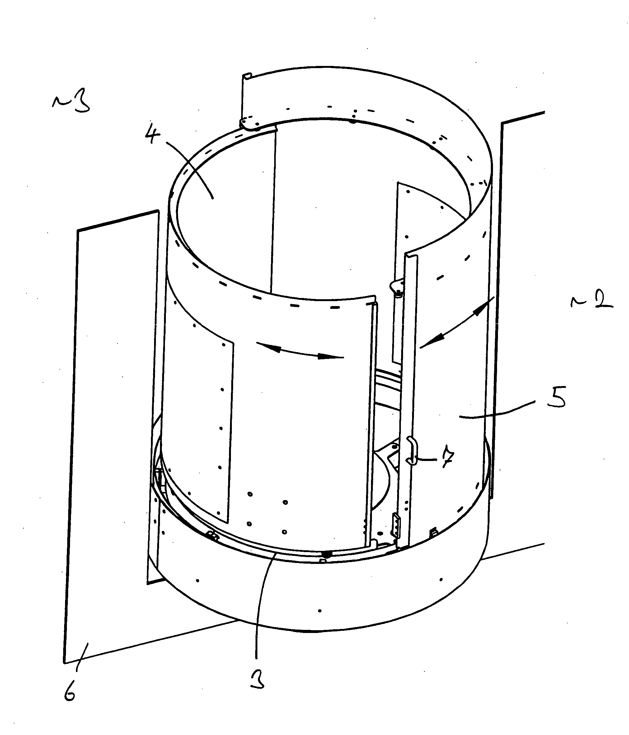
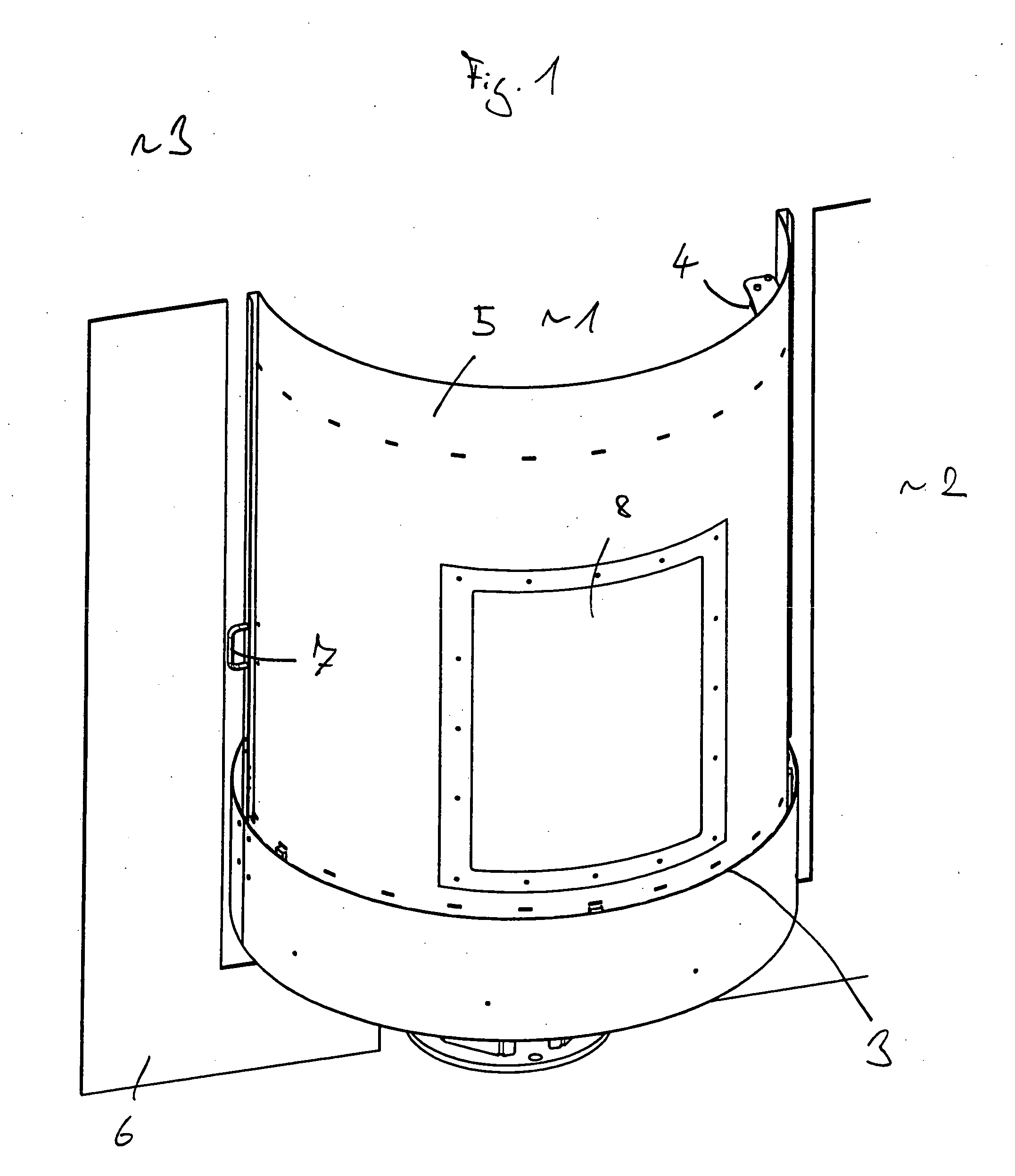
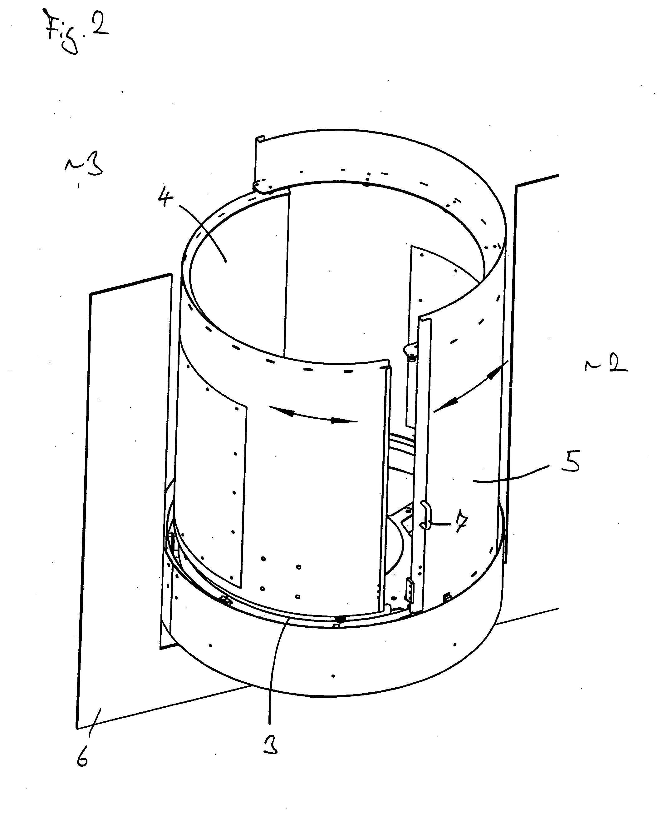
[0027]FIG. 1 shows an embodiment of the loading station in accordance with the invention comprising a loading region 1 which is accessible from a loading side 2 and from a machine side 3 in dependence on the position of the door elements 4 and 5. The door elements thus have a machine position in which they release the machine side and close the loading side and a loading position in which they release the loading side and close the machine side. The loading station is integrated in this connection into a partition wall 6 which separates the loading side 2 from the machine side 3. In this connection, the loading station forms a sluice between the loading side and the machine side and thus enables a safe transfer of objects from the loading region into the machine region and vice versa in that, in the loading position, objects are introduced into the loading region from the loading side, the door elements are moved into the machine position and the objects are then taken over from the...


PUM


Abstract

The present invention relates to a loading station comprising a loading region which is accessible from a loading side and from a machine side and comprising two door elements movable along a guide from a machine position in which they release the machine side and close the loading side into a loading position in which they release the loading side and close the machine side, wherein the door elements overlap at least partially in the loading position and/or in the machine position so that, on an opening procedure of the machine side and/or of the loading side, the machine side and/or the loading side only starts to open when the respective other side has closed at least partially.

Description

BACKGROUND OF THE INVENTION[0001]The present invention relates to a loading station comprising a loading region which is accessible from a loading side and from a machine side.[0002]Such loading stations are used e.g. with automatic handling systems or flexible machining cells to supply workpieces which are e.g. located on a pallet safely into the system for storage, machining or other handling. In this process, automated transport machinery or processing machinery are typically provided at the machine side, e.g. to automatically store the workpieces in a store or to machine them automatically at a processing machine.[0003]The loading region in the loading station in accordance with the invention can be closed in this context toward the loading side and toward the machine side by door elements to prevent any injury of operating personnel. The door elements thus have a machine position in which they release the machine side and close the loading side and a loading position in which t...

Claims


Application Information

Patent Timeline
IPC IPC(8): E06B3/90
CPCB23Q11/0891B23Q11/0833B23Q2210/006F16P3/08
Inventor LANDERER, ROMAN
Owner LIEBHERR VERZAHNTECHNIK GMBH
Why Eureka
Try Eureka