Micromachine and Method for Manufacturing the Same

Inactive Publication Date: 2009-06-11
SEMICON ENERGY LAB CO LTD
View PDF2 Cites 53 Cited by
  • Summary
  • Abstract
  • Description
  • Claims
  • Application Information

AI Technical Summary

Benefits of technology

[0019]According to the present invention, in a micromachine (MEMS structure body) which is formed with a surface micromachining technology, a wiring (an upper auxiliary wiring) formed over a sacrificial layer is electrically connected to a different wiring (an upper connectio

Problems solved by technology

However, in the MEMS structure body, because the sacrificial layer is very thick, it is difficult to control a process to achiev

Method used


Image

  • Micromachine and Method for Manufacturing the Same
  • Micromachine and Method for Manufacturing the Same
  • Micromachine and Method for Manufacturing the Same

Examples


embodiment mode 1

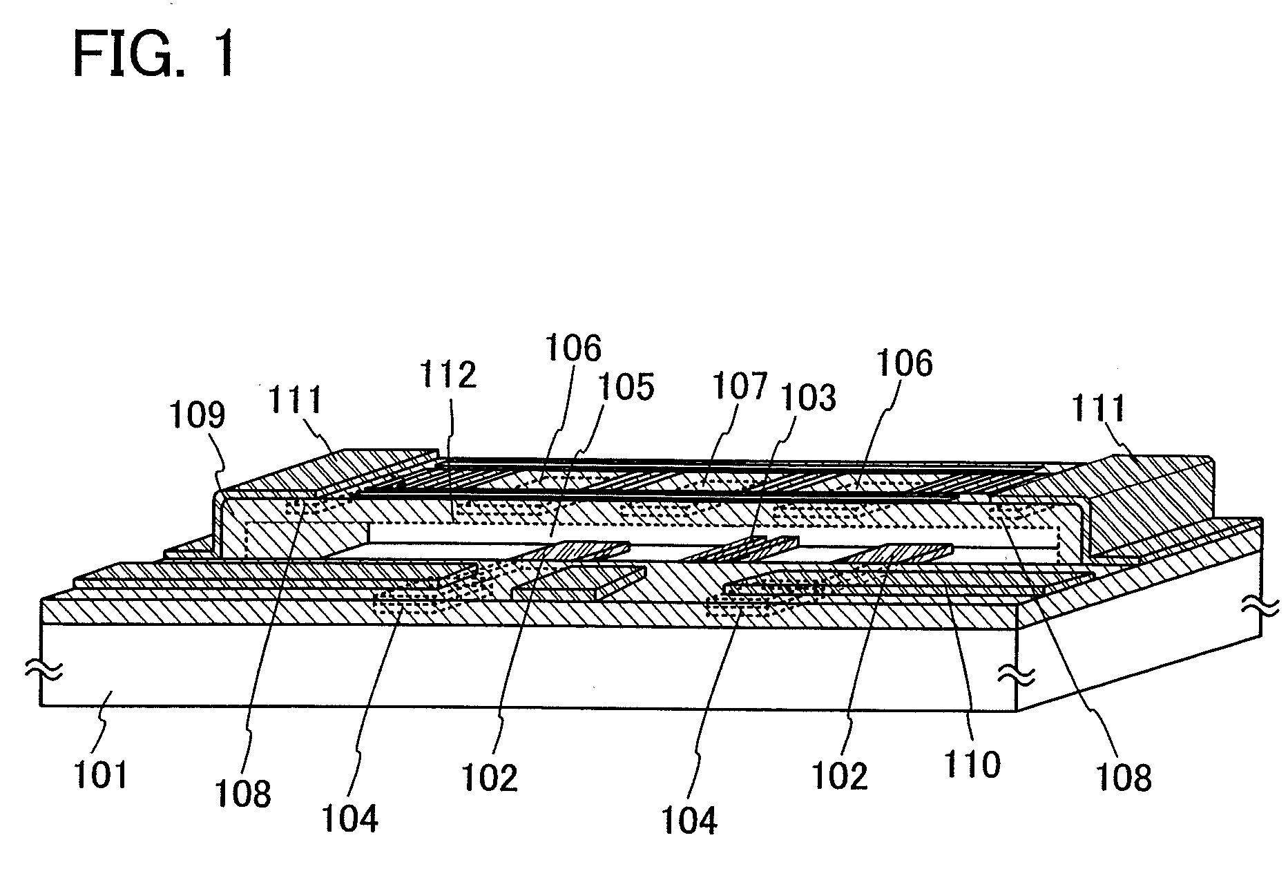
[0026]In Embodiment Mode 1, a structure of a microelectromechanical system (MEMS) switch which is a micromachine according to the present invention will be described.

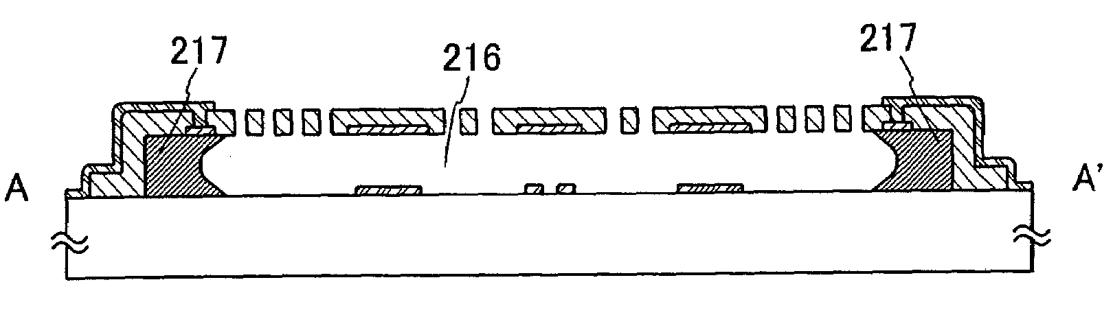
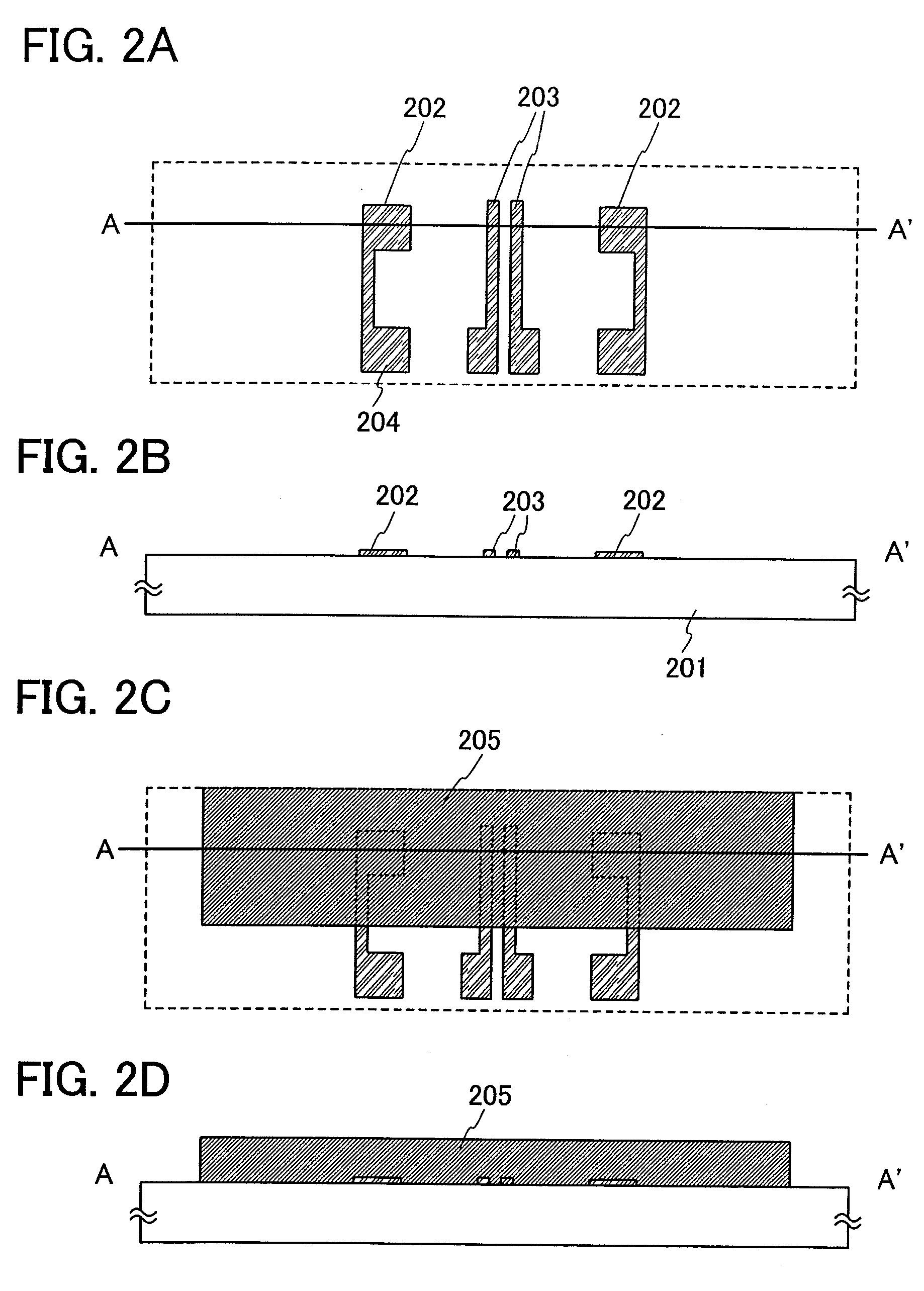
[0027]As illustrated in FIG. 1, in a MEMS switch, lower driving electrodes 102, a lower switch electrode 103, and lower auxiliary wirings 104 are provided over a substrate 101 having an insulating surface. Further, upper driving electrodes 106, an upper switch electrode 107, and upper auxiliary wirings 108 are provided over the lower driving electrodes 102, the lower switch electrode 103, and the lower auxiliary wirings 104 with a space 105 interposed therebetween. The upper driving electrodes 106, the upper switch electrode 107, and the upper auxiliary wirings 108 are formed to be integrated with a structural layer 109. In FIG. 1, a cross section of the structural layer 109 is partly illustrated by a dashed line 112 to make the description more detailed, but the structural layer 109 actually covers an upper part of the...


PUM

PropertyMeasurementUnit
Thicknessaaaaaaaaaa
Thicknessaaaaaaaaaa
Thicknessaaaaaaaaaa

Abstract

A structure which prevents thinning and disconnection of a wiring is provided, in a micromachine (MEMS structure body) formed with a surface micromachining technology. A wiring (upper auxiliary wiring) over a sacrificial layer is electrically connected to a different wiring (upper connection wiring) over the sacrificial layer, so that thinning, disconnection, and the like of the wiring formed over the sacrificial layer at a step portion generated due to the thickness of the sacrificial layer can be prevented. The wiring over the sacrificial layer is formed of the same conductive film as an upper driving electrode which is a movable electrode and is thus thin. However, the different wiring is formed over a structural layer, which is formed by a CVD method and has a rounded step, and has a thickness of 200 nm to 1 μm, whereby thinning, disconnection, and the like of the wiring can be further prevented.

Description

BACKGROUND OF THE INVENTION[0001]1. Field of the Invention[0002]The present invention relates to a structure of a micromachine which is formed with a microelectromechanical system (MEMS) technology.[0003]2. Description of the Related Art[0004]These days, MEMS switches which utilize a MEMS technology, and sensors, resonators, communication devices, and the like which are provided with the MEMS switches have been attracting attention.[0005]These are also called micromachines, and there are two kinds of technologies, a surface micromachining technology and a bulk micromachining technology, depending on manufacturing methods. In the surface micromachining technology, thin films are stacked over a substrate and then processed by a photolithography method or an etching method, whereby a MEMS structure body can be formed. Further, in the bulk micromachining technology, a silicon wafer or a silicon on insulator (SOI) substrate itself is processed by etching or polishing, whereby a MEMS stru...

Claims


Application Information

Patent Timeline
IPC IPC(8): H05K1/09H05K1/00H05K3/10
CPCB81B2201/018B81C1/00166H01H1/58Y10T29/49155H01H2001/0052H01H2001/0057H01H59/0009
Inventor MIKAMI, MAYUMIIZUMI, KONAMI
Owner SEMICON ENERGY LAB CO LTD
Why Eureka
Try Eureka